Table of Contents
Advertisement
Advertisement
Table of Contents

Related Manuals for natus OLYMPIC STERILE-DRIER 43

Summary of Contents for natus OLYMPIC STERILE-DRIER 43
- Page 1 Instruction Manual OLYMPIC STERILE-DRIER Model 43/44 Read and be familiar with this manual before installing, operating, or servicing this device. To ensure operator, CAUTION technician, and patient safety, use only as specified in this manual. 602018C...
- Page 3 The information in this manual is subject to change without notice. No part of this manual may be photocopied, reproduced, translated, or reduced to any electronic medium without the express written permission of Natus Medical Incorporated. All tradenames and trademarks mentioned herein are property of their respective owners.
-
Page 5: Table Of Contents
Contents Section Overview ........1-1 Conventions . - Page 6 Section Troubleshooting ....... . 5-1 Technical Support......... . . 5-2 Section Service .
-
Page 7: Section 1 Overview
S e c t i o n Overview This manual provides the necessary information to install, maintain, and service the Olympic Sterile-Drier Model 43/44. The installation and service instructions in this manual are intended for use by qualified service technicians. Conventions The following conventions are used in this manual. -
Page 8: Intended Use
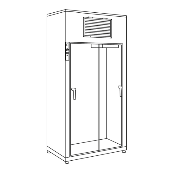
Intended Use Intended Use Olympic Driers are intended to rapidly dry pasteurized medical equipment, primarily respiratory therapy and anesthesia parts. The Drier should be used after disinfection by pasteurization or liquid chemical means. Sterile-Driers are not intended for storing or warming solutions. CAUTION Description Sterile-Driers use HEPA filtered, heated air to dry parts. -
Page 9: Accessories
Accessories Accessories Natus Medical offers the following items that are compatible for use with the Sterile-Drier. To order these items, see page 7-1. Tube Holder: Slide out tube holder is capable of holding 35 1-in. diameter tubes. Standard Bag Drier: Adapter fits in any Sterile-Drier that holds 16 breathing bags. - Page 10 Accessories OLYMPIC STERILE-DRIER Model 43/44 Instruction Manual...
-
Page 11: Section 2 Installation
S e c t i o n Installation Only qualified technicians should install this device. Read and be familiar with this instruction manual before installing this device. CAUTION Installing the Drier Space Requirements Sterile-Drier Model 43 Dimensions: 26-in. wide x 20.5-in. deep x 86-in. high (66-cm wide x 52-cm deep x 218-cm high) Rear clearance: 2-in.;... -
Page 12: Electrical Requirements
Assembly Electrical Requirements The Olympic Sterile-Drier Model 43 is available in the following configurations: 120V~, 60 Hz, 8A (standard configuration for the United States and Canada) 100V~, 50 Hz, 9.5A 100V~, 60 Hz, 9.5A 220-230V~, 50 Hz, 4.5A 220-230V~, 60 Hz, 4.5A The Olympic Sterile-Drier Model 44 is available in the following configurations: 120V~, 60 Hz, 16A (standard configuration for the United States and Canada) 100V~, 50 Hz, 18A... -
Page 13: Installing The Floor Anchors
Assembly Figure 2.1 Anchor holes in the Driers Anchor holes Leveling feet (x4) Model 43 Model 44 Installing the Floor Anchors The Drier must be anchored to the floor. All Driers have two anchor holes drilled into the base plate to anchor the Drier (see Figure 2.1). Figure 2.2 Anchor holes in the floor, Model 44 6.0 in. -
Page 14: Venting
Inspecting the Heaters Venting Standard Driers vent to room air and no special venting is required. If special venting is desired, a vent adapter is available as an option (see Figure 2.4). The vent requires a four-inch (10-cm) hose. Connect the hose to the vent adapter using a standard hose clamp, then connect the opposite end of the hose to a hospital exhaust vent at normal atmospheric pressure. - Page 15 Inspecting the Heaters Figure 2.5 Location of screws Screw locations (x4) Screw locations (x6) Pull out and remove the front cover (Figure 2.6). Electrical shock hazard when the front panel is removed. WARNING In Model 44, the left and right plenum assemblies are mirror images of one another. For example, the thermal cut-out on the right plenum assembly is located on the back, while NOTE that on the left is visible from the front.
-
Page 16: Testing The Drier
Testing the Drier Figure 2.7 Accessing the blower assembly Note: Pull together the two springs to unlatch them, and then separate. Lift the metal box up to access the heaters. Plenum assembly HEPA filter FRONT Blower Blower bracket Acorn nuts and washers Blower filter plate Separate the plenum from the casing (or HEPA filter), and then lift the plenum and unscrew the heater from the socket. - Page 17 Testing the Drier Turn the power switch to the (O) position. Set the timer to 30 minutes by pressing . Observe for 60 seconds, verifying that the timer counts down the remaining minutes. If the device does not operate as expected, see Troubleshooting on page 5-1. NOTE OLYMPIC STERILE-DRIER Model 43/44 Instruction Manual...
- Page 18 Testing the Drier OLYMPIC STERILE-DRIER Model 43/44 Instruction Manual...
-
Page 19: Section 3 Operation
S e c t i o n Operation Explosion hazard. Do not use this device in the presence of flammables (e.g., oxygen, nitrous oxide, anesthetics). WARNING Read and be familiar with this instruction manual before using this device. Connect this device directly to a properly grounded hospital-grade outlet. CAUTION Inner metal surfaces are hot when the Drier is on. -
Page 20: Drying Tubes
Operating the Drier Drying Tubes To insert the tube holder: Pull the release pin while sliding the tube holder back into the bracket. To dry tubes: Pull the tube holder forward until it stops (see Figure 3.1). Figure 3.1 Tube holder Tube holder NOTE: This surface must be in front of the... -
Page 21: Main Power Switch
Operating the Drier Main Power Switch Use the main power switch to turn the device power on or off (see Figure 3.2). The power may be left on continuously; the control circuitry uses little power. NOTE Temperature Control The thermostat controls air temperature within the drying cabinet. To operate the temperature control, push the knob in while rotating to turn the indicator from (1) to (10) (see Figure 3.2). - Page 22 Operating the Drier OLYMPIC STERILE-DRIER Model 43/44 Instruction Manual...
-
Page 23: Section 4 Maintenance
S e c t i o n Maintenance Electrical shock hazard when the enclosure is open. Unplug the power cord from the electrical outlet before cleaning this device. WARNING Only qualified technicians should perform maintenance procedures. Never use alcohol to clean the Plexiglas door as alcohol will damage the plastic. CAUTION Do not allow liquid to enter the louver prefilter cover to avoid damaging the internal filter system. -
Page 24: Periodic Maintenance
Periodic Maintenance Periodic Maintenance Changing the Prefilter To keep the drier in optimal operating condition, change the prefilter every two to three months. Required Items: Screwdriver Prefilter (set of 6) (part no. 54308) To change the prefilter: Loosen the bottom screws of the louver (see Figure 4.1). Figure 4.1 Accessing the prefilter Louver... - Page 25 Semi-Annual Maintenance Figure 4.2 Location of screws Screw locations (x4) Screw locations (x6) Pull out and remove the front cover (see Figure 4.3). Electrical shock hazard when the enclosure is open. Unplug the power cord from the electrical outlet before cleaning this device. WARNING Figure 4.3 Removing the front cover...
- Page 26 Semi-Annual Maintenance Figure 4.4 Accessing the blower HEPA filter FRONT Blower Blower bracket Acorn nuts and washers (x4) Blower filter plate Apply oil at the lubrication points (see Figure 4.5). Figure 4.5 Blower lubrication points Lubrication points (x2) Place the blower bracket into position, then reattach the hardware (see step 5). Place the front cover into position, tighten the screws, then push the upper white door seal into position.
-
Page 27: Every Three Years
Every Three Years Every Three Years Replacing the HEPA Filter Use caution when handling the HEPA filter to avoid damaging it. Upon receipt of new HEPA filters, inspect both sides for holes, tears, or rips—these conditions eliminate the NOTE effectiveness of HEPA filters. Required Items: HEPA filter (part no. - Page 28 Every Three Years Reconnect the power cord to the electrical outlet. Test the HEPA filter and seal after installation. CAUTION OLYMPIC STERILE-DRIER Model 43/44 Instruction Manual...
-
Page 29: Section 5 Troubleshooting
S e c t i o n Troubleshooting Should you experience difficulty when operating your Drier, consult the following table. For problems not listed in the table, contact Natus Medical (see page 5-2). Table 5.1 Troubleshooting chart Problem Probable Cause... -
Page 30: Technical Support
PCB Thermostat probe Replace the thermostat probe assembly failed assembly (see page 6-6). Technical Support For technical support, contact Natus Medical at: Toll-free: 1-866-940-7143 (US/Canada) Phone: +1-206-767-3500 (international) Fax: +1-206-767-0573 Email: Seattle_technical_service@natus.com OLYMPIC STERILE-DRIER Model 43/44 Instruction Manual... -
Page 31: Section 6 Service
To ensure performance to factory specifications, it is recommended that all replacement parts be those either manufactured or sold by Natus Medical. After all repair actions and tests are complete, perform the pre-operative test procedure in this manual (see page 2-4) to ensure proper operation and compliance with published specifications. -
Page 32: Replacing The Main And Transformer Fuses
Repair Procedures Replacing the Main and Transformer Fuses If the device is plugged in but won’t turn on, the fuse may have to be replaced. Replace the fuse only with a new fuse of the same type and value. CAUTION Required Items: Fuse (part no. -
Page 33: Replacing The Heater
Repair Procedures Replacing the Heater If the heater fails to warm the air, it may need to be replaced. Model 43 Driers have two heaters; Model 44 Driers have four heaters. Ensure that the proper voltage and wattage heater is being replaced into the correct socket. -
Page 34: Replacing The Control Panel Printed Circuit Board
Repair Procedures Replacing the Control Panel Printed Circuit Board If the indicator lights don’t work, the blower doesn’t run, or the heater doesn’t warm the air, the control panel printed circuit board (PCB) may need to be replaced. PCBs are electrostatic discharge (ESD) sensitive equipment. Use appropriate precautions to prevent ESD. - Page 35 Repair Procedures From the side access panel, locate and remove the kep nuts (x2) that secure the front control access panel assembly to the front column (see Figure 6.1). From inside the blower access upper cabinet, remove the kep nut attached to the top of the control panel.
-
Page 36: Replacing The Thermal Probe
Repair Procedures Replacing the Thermal Probe ESD-sensitive equipment. Use appropriate precautions to prevent ESD. CAUTION Required Items: Thermal probe (part no. 401129) Screwdriver Masking tape Electrical grounding strap Cable tie To remove the thermal probe: Press the power switch to the (O) position, then unplug the power cord. - Page 37 Repair Procedures Locate the thermal probe inside the tube holder, mounted on the screen. Using a piece of masking tape, mark the exact location where the thermal probe is attached to the screen—this location is important for accurate temperature readings. Cut and remove the cable tie from the probe.
-
Page 38: Replacing The Heater Control Relay K2
Repair Procedures Connect the thermal probe cable connector (wires 27, 29, and 30) to J3 on the control panel PCB. Remove slack from the thermal probe cable by gently pulling the excess cable into the upper cabinet. Ensure that the cable is not dangling behind the tube holder. NOTE Secure the probe cable to the two cable tie mounts with cable ties. - Page 39 Repair Procedures Figure 6.3 Disconnecting the heater control relay Heatsink Screw Connector bracket Wire #9 at Star terminal #1 washers Wire #28 at terminal #4 Wire #11 at terminal #2 Double wire Wire #25 at Screws (x2) at terminal terminal #3 secure relay to #2 (Model heatsink...
-
Page 40: Replacing The Blower Control Relay
Repair Procedures Replacing the Blower Control Relay (Model 44 only) If the timer is on, but the blower doesn’t operate, replace the blower control relay. Required Items: Blower control relay (part no. 200041) Screwdriver To replace the blower control relay: Press the power switch to the (O) position, then unplug the power cord. -
Page 41: Replacing The Blower/Blower Motor
Repair Procedures Replacing the Blower/Blower Motor If the blower or its motor fail, it should be replaced. For 60Hz devices only, the blower motor (rather than the entire blower assembly) may be replaced, follow step 8a through step 8h. NOTE Required Items: Blower, 50Hz (part no. - Page 42 Repair Procedures Figure 6.4 Accessing the blower assembly HEPA filter FRONT Blower Blower bracket Acorn nuts and washers Blower filter plate Lift the blower assembly and position it to allow access to the ground wire screw on the motor side of the blower housing. Remove and save the ground screw and star lock washer.
- Page 43 Repair Procedures Loosen the set screw, then remove the squirrel cage from the blower assembly (see Figure 6.6). Figure 6.6 Accessing the set screw Allen (or Torx) driver should be placed through blower opening and slot in squirrel cage to access the set screw.
-
Page 44: Testing The Thermal Cut-Out Function
Repair Procedures Install the new blower assembly or old blower assembly with new motor installed onto the blower filter plate with the mounting hardware. Connect the wires (see the appropriate wiring diagram in Appendix A). Press the red button on the thermal cut-out to reset if tripped (see Figure 6.7). Figure 6.7 Thermal cut-out Thermal cut-out... -
Page 45: Replacing The Thermal Cut-Out
Repair Procedures 120V~ configurations. For other power configurations, see the current ratings in Section 8. Block the airflow from the blower into the plenum by placing the metal plate between the blower and the plenum gasket (see Figure 6.8). Figure 6.8 Placing the metal plate Plenum Blower assembly... - Page 46 Repair Procedures Pull out and remove the front cover (see Figure 4.3 on page 4-3). Electrical shock hazard when the front panel is removed. WARNING In Model 44, the left and right plenum assemblies are mirror images of one another. For example, the thermal cut-out on the right plenum assembly is located on the back, while NOTE that on the left is visible from the front.
-
Page 47: Section 7 Replacement Parts
S e c t i o n Replacement Parts Only use Natus Medical–approved parts with the Drier. NOTE Ordering Information To order parts and accessories, contact: Natus Medical Incorporated Customer Service Department Toll-free: 1-800-303-0306 Phone: +1-650-802-0400 Fax: +1-650-802-6620 Email: customer_service@natus.com Parts and Accessories When ordering, provide the item number and your Drier’s model number to the... - Page 48 Ordering Information Table 7.1 Parts and accessories, continued Item Name / Description Item Number Blower assembly, 60Hz 200036 Blower control relay 200041 Blower gasket P91800 Blower motor (60Hz only) P91278 Blower relay socket (Model 44) 200165 Core, tube holder 300120 Door assembly 400061 Door seal...
-
Page 49: Section 8 Specifications
S e c t i o n Specifications Model 43 and Model 44 (220-230V)* Intended Use Olympic Driers are intended to rapidly dry Voltage: 220-230V~, single phase pasteurized medical equipment, primarily Consumption: respiratory therapy and anesthesia parts. The Drier 4.5A (Model 43) should be used after disinfection by pasteurization or other liquid chemical means. - Page 50 Controls Service Mains power changes device state mains power Service can be performed by hospital technicians. (|) or See Ordering Information on page 7-1 for more information. dial is a thermostat control for the SET TEMP internal temperature of the Drier Warranty One-year warranty.