Table of Contents
Advertisement
Advertisement
Table of Contents

Related Manuals for Nedap Transit Ultimate

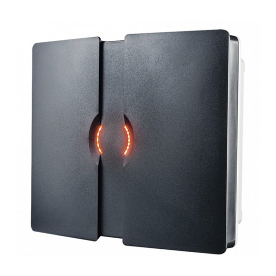
Summary of Contents for Nedap Transit Ultimate
- Page 1 TRANSIT ULTIMATE installation guide 2017-08-17 | v5.01 | 5481104...
-
Page 2: Table Of Contents
2. INSTALLATION ________________________________________________________ 5 SAFETY PRECAUTIONS ___________________________________________ 5 INSTALLATION GUIDELINES _______________________________________ 5 MOUNTING INSTRUCTIONS _______________________________________ 6 2.3.1 TRANSIT ULTIMATE DIMENSIONS ____________________________ 6 2.3.2 WALL MOUNTING _________________________________________ 7 2.3.3 POLE MOUNTING__________________________________________ 8 2.3.4 WEATHER PROTECTION HOOD ______________________________ 9 INSTALLING THE SECURITY KEY PACK _____________________________ 10 INSTALLING A COMMUNICATION BOARD ___________________________ 11 3. -
Page 3: Introduction
Read range adjustment The reader efficiently resolves typical multi-lane, entry and exit reader challenges. The read range of the TRANSIT Ultimate can be adjusted to offer secure and reliable identification in demanding applications. Housing & mounting The TRANSIT Ultimate is intended for outdoor installation. -
Page 4: Ultimate Features
INTRODUCTION ULTIMATE FEATURES Encrypted tag authentication The TRANSIT Ultimate enables encrypted tag authentication for the Ultimate tags: Smartcard Booster Ultimate, LEGIC Booster Ultimate and Window Tag Ultimate. The authentication uses encryption based upon AES 128-bit keys. Key diversification is used to ensure that a unique encryption key is used for every tag. -
Page 5: Installation
NEDAP N.V. INSTALLATION GUIDELINES The TRANSIT Ultimate can be installed in any position. The normally expected read range is up to 10 meters. Usually the reader is mounted in the horizontal position. In this case the coverage area in the horizontal plane is maximized. -
Page 6: Mounting Instructions
See the following chapters for details about the dimensions of the reader and the mounting brackets and the locations of the mounting positions. 2.3.1 TRANSIT ULTIMATE DIMENSIONS The picture below shows the dimensions of the TRANSIT Ultimate. All dimensions are in mm. 326 mm... -
Page 7: Wall Mounting
Mounting Set is assembled mount it to the wall (or to the Pole Mounting Set) based on the dimensions in Figure 3. The TRANSIT Ultimate can be “aimed” with the Wall Mounting Set and when the bolts are tightened, it will stay in place. -
Page 8: Pole Mounting
2.3.3 POLE MOUNTING The Pole Mounting Kit has to be ordered separately (art. no. 5626595). The TRANSIT Ultimate can be mounted to round poles with maximum diameter of 190 mm and square poles with maximum diameter of 150 mm using the Pole Mounting Kit. -
Page 9: Weather Protection Hood
TRANSIT ULTIMATE | INSTALLATION GUIDE INSTALLATION 2.3.4 WEATHER PROTECTION HOOD The Weather Protection Hood has to be ordered separately (art. no. 9218327). It is recommended when the reader is installed in places where direct sunlight may overheat the reader. 75 mm... -
Page 10: Installing The Security Key Pack
The optional Security Key Pack (SAM) has to be ordered separately (art. no. 9216537) and is required for the TRANSIT Ultimate to perform the encrypted authentication on the Ultimate tags. Please follow the procedure below to install the Security Key Pack into the TRANSIT Ultimate. -
Page 11: Installing A Communication Board
Make sure to follow all safety precautions outlined in chapter 2.1 when installing or replacing a communication board. Communication board installation procedure: Open the TRANSIT Ultimate. You can put the cover strut into place to keep the cover open. Disconnect the power supply. -
Page 12: Connections
See chapter 3.3 Read-disable input Relay output See chapter 3.4.2 See chapter 3.4.1 Tamper switch General purpose inputs See chapter 3.4.3 See chapter 3.4.4 Proximity antenna Antenna modulation See chapter 3.5.1 See chapter 3.5.2 Figure 7: TRANSIT Ultimate connections overview 12/36... -
Page 13: Power Supply
TRANSIT ULTIMATE | INSTALLATION GUIDE CONNECTIONS POWER SUPPLY The TRANSIT Ultimate can be powered by AC mains or by a 24 VDC power supply. 3.2.1 AC MAINS Connect the Mains load and neutral wires to the connector terminals VAC-L and VAC-N. -
Page 14: Dc Output
TRANSIT ULTIMATE | INSTALLATION GUIDE CONNECTIONS 3.2.3 DC OUTPUT The DC output can be used to supply power to an additional device installed inside or near the TRANSIT Ultimate. +DC-OUT Figure 10: DC output connections DC output ratings Output voltage: 23.4 VDC ± 10% Max. -
Page 15: Communication
CONNECTIONS COMMUNICATION 3.3.1 USB The TRANSIT Ultimate features an USB interface for service and installation purposes. The USB connector (Type B) is accessible behind the cover. While the USB interface is in use, the optional communication interface board is disabled. -
Page 16: Wiegand / Magstripe / Barcode
TRANSIT ULTIMATE | INSTALLATION GUIDE CONNECTIONS 3.3.2 WIEGAND / MAGSTRIPE / BARCODE The synchronous communication interface wiring uses the connections described below. The actual protocol output depends upon the reader firmware. Please refer to the firmware manual for more details. -
Page 17: Rs232 Communication
TRANSIT ULTIMATE | INSTALLATION GUIDE CONNECTIONS 3.3.3 RS232 COMMUNICATION TRANSIT SIDE PC SIDE DIN 25 Name DIN 9 Name Cable specification: 3 x 0.25mm shielded Maximum cable length: 30 meter. 3.3.4 RS422 COMMUNICATION RS422 RS485 Jumper in position RS422. Jumper in position RS485. -
Page 18: Digital I/O
TRANSIT ULTIMATE | INSTALLATION GUIDE CONNECTIONS DIGITAL I/O 3.4.1 RELAY OUTPUT The relay output is automatically activated upon successful identification / authentication of a transponder. The automatic-relay-activation-mode can be configured using the firmware. Please refer to the firmware manual for more details. -
Page 19: Read Disable Input
CONNECTIONS 3.4.2 READ DISABLE INPUT The reading of the TRANSIT Ultimate can be completely disabled with the read disable input (RDIS). This input is commonly used in combination with a sensor (e.g. inductive loop) that detects the presence of a person or vehicle. Use always a relay contact to connect the internal 5V to the RDIS input. -
Page 20: Tamper Switch
CONNECTIONS 3.4.3 TAMPER SWITCH The TRANSIT Ultimate features an internal tamper switch that indicates when the cover is opened. This contact may be connected to an external alarm system. The contacts are normally closed when the cover is in place. -
Page 21: General Purpose Inputs
TRANSIT ULTIMATE | INSTALLATION GUIDE CONNECTIONS 3.4.4 GENERAL PURPOSE INPUTS Three general purpose inputs are available on the TRANSIT Ultimate. The inputs are active low. No external voltage should be applied to the inputs. Connect to ground to activate or otherwise leave unconnected. -
Page 22: Special Connections
SPECIAL CONNECTIONS 3.5.1 PROXIMITY ANTENNA Optionally a NEDAP proximity antenna can be connected to the TRANSIT Ultimate to enable simultaneously long-range and proximity identification. This is useful when controlling a gate where vehicles as well as pedestrians, cyclists and/or motorists can enter. -
Page 23: Nedap Antenna Modulation
TRANSIT ULTIMATE | INSTALLATION GUIDE CONNECTIONS 3.5.2 NEDAP ANTENNA MODULATION The Nedap antenna modulation interface is used to connect the TRANSIT Ultimate to NEDAP AEOS access control hardware such as the AP1001. Instead of a proximity antenna the TRANSIT Ultimate can be connected. -
Page 24: Configuration
TRANSIT ULTIMATE | INSTALLATION GUIDE CONFIGURATION CONFIGURATION FIRMWARE OPTIONS The TRANSIT Ultimate supports the same firmware versions as the TRANSIT Standard. Different firmware versions are available to support different features and communication protocols. For each firmware version a separate installation guide is available. -
Page 25: Ultimate-Mode
The TRANSIT Ultimate can operate in the ULTIMATE-mode or in the NORMAL-mode. In the NORMAL-mode the TAB board is bypassed. The reader is compatible with the TRANSIT Standard. In this mode the TRANSIT Ultimate can read original tags, such as Compact-Tag, Window-Button, Heavy-Duty-Tag and Boosters. Also the Ultimate-tags will work, but no authentication or other Ultimate functions are performed. -
Page 26: Frequency Selection
It may also be required to select a different frequency to avoid disturbance between the TRANSIT Ultimate and other 2.45GHz equipment, such as Wi-Fi access points. Please also read chapter 4.7 when experiencing interference. -
Page 27: Read Range Control
CONFIGURATION READ RANGE CONTROL The read range of the TRANSIT Ultimate can be controlled with the embedded squelch function. The squelch references the received signal strength against the squelch level setting. When the received signal strength is below the squelch level no identification is possible. -
Page 28: Microwave Time-Sharing
TRANSIT ULTIMATE | INSTALLATION GUIDE CONFIGURATION MICROWAVE TIME-SHARING The microwave antenna of the TRANSIT Ultimate is continuously on. This will ensure the fastest identification times. However it may cause interference on other 2.45GHz equipment. Enable the microwave time-share mode to only use the selected frequency periodically (the reader automatically switches on and off). -
Page 29: Led Indications
TRANSIT ULTIMATE | INSTALLATION GUIDE LED INDICATIONS LED INDICATIONS MAIN BOARD INDICATIONS A number of LEDs on the main board of the TRANSIT Ultimate indicate the status of the reader. The list below describes the function of each LED. Read disable LEDs... -
Page 30: Tab Board Indications
Only indicated when using Ultimate tags. GOOD Ultimate tag successfully authenticated. Tag data transmitted to TRANSIT Ultimate main board. TRANSIT should be able to identify now. Check ID-LED main board. Transmit serial data (USB, I/F-board). See chapter 4.2. Receive serial data (USB, I/F-board). -
Page 31: Atechnical Specifications
Access Control Performance Line security: Level 1 Destructive attack: Level 1 Endurance: Level 4 Standby Power: Level 1 This Transit Ultimate reader must be connected and controlled by a UL listed controller (e.g. AP4803X). (*) not evaluated by UL 31/36... -
Page 32: Bfrequency Channels
TRANSIT ULTIMATE | INSTALLATION GUIDE Frequency Channels FREQUENCY CHANNELS Transceiver board frequency channel selection table: Display value Frequency (GHz) Wi-Fi ETSI 2.4360 2.4366 2.4372 2.4378 2.4384 2.4390 2.4396 2.4402 2.4408 2.4414 ... -
Page 33: Cnedap Part Numbers
TRANSIT ULTIMATE | INSTALLATION GUIDE Nedap Part Numbers NEDAP PART NUMBERS Product Part number Description 9215689 TRANSIT Ultimate 9216537 Security Key Pack (SAM) 5626595 Pole Mounting Kit 9218327 Weather Protection Hood 7819102 HID Interface Board (HIB) 7817940 TCP/IP Interface Board (*) -
Page 34: Dfcc / Ic Statement
TRANSIT ULTIMATE | INSTALLATION GUIDE FCC / IC Statement FCC / IC STATEMENT FCC ID: CGDTRANSITULT2 1444A-TRANSITULT2 FCC ID: CGDTRANSITULTI 1444A-TRANSITULTI Compliance statements (part15.19) This device complies with part 15 of the FCC Rules and to RSS210 of Industry Canada. Operation is subject to the... -
Page 35: Edisclaimer
TRANSIT ULTIMATE | INSTALLATION GUIDE Disclaimer DISCLAIMER This information is furnished for guidance, and with no guarantee as to its accuracy or completeness; its publication conveys no license under any patent or other right, nor does the publisher assume liability for any consequence of its use;... -
Page 36: Fdocument Revision
TRANSIT ULTIMATE | INSTALLATION GUIDE Document revision DOCUMENT REVISION Version Date Comment 5.01 2017-08-17 HR: updates for changed transceiver board 4.10 2017-07-17 HR: added outdoor use statement 4.09 2016-10-06 HR: added time sharing chapter 4.08 2016-08-08 HR: weather protection hood added 4.07...