
Related Manuals for Eclipse BrightFire 200 series


Summary of Contents for Eclipse BrightFire 200 series
- Page 1 Eclipse BrightFire 200 Burners BRT Size G, M, and B Operating Instructions Edition 09.15 Version 1...
- Page 2 Please send your corrections and comments to our Technical Documentation Specialist. Product Name Item # It must be understood that Eclipse’s liability for its product, DD MMM YYYY whether due to breach of warranty, negligence, strict liability, or otherwise is limited to the furnishing of...
-
Page 3: Table Of Contents
Table of Contents Introduction ............................. 4 Product Description ......................4 Benefits ..........................4 Audience ..........................4 BrightFire Documents......................4 Purpose ..........................4 Safety..............................5 Capabilities........................... 5 Operator Training ......................... 5 Replacement Parts....................... 5 Installation ............................6 Handling & Storage ......................6 Approval of Components...................... -
Page 4: Introduction
It can be installed in either end-fired or cross- fired furnaces, as well as in under port or side-of-port These aspects are: configurations. It is designed to work with the Eclipse • Installation Gimbal Mounting Bracket to provide excellent adjust- •... -
Page 5: Safety
Replacement Parts ■ Eclipse recommends installing a safety guard around moving parts. Order replacement parts from Eclipse only. All Eclipse approved valves or switches should carry UL, FM, CSA, ■ Eclipse recommends considering any area with CGA and/or CE approval where applicable. -
Page 6: Installation
Installation Gas Piping In this section you will find information and instructions needed to install the burner and the system components. All the gas piping must comply with all applicable local Handling & Storage codes and/or standards such as: Handling •... -
Page 7: Brightfire 200 Adjustable Burners
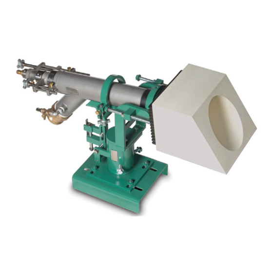
BrightFire® 200 Adjustable Burners 4. Install the alignment tube in the bracket, ensuring that the alignment tube pin is in contact with the gimbal ring ® The BrightFire 200 is available in three body sizes, G, M of the bracket to simulate burner position and allow for and B, with diameters of 73.0 mm (2.88”), 88.9 mm (3.50”) proper working distance from the socket plate to the and 101.6 mm (4.00”), respectively. -
Page 8: Brightfire 200 Installation And Start-Up During Initial Heat-Up Furnace
• Ensure local gas and cooling air valves are closed. The main gas and cooling air supplies should remain closed until the main burners are to be brought on line. • Confirm that the burner blocks are plugged prior to, and during, heat-up. -
Page 9: Brightfire 200 Installation To Convert Existing Burners
19. With all of the main burners in operation, a preliminary Start of Outer Nozzle Taper gas flow balance may now be achieved and will vary based on furnace design and/or the desired input or temperature profile of the furnace. This should be done with the gas control in manual. - Page 10 6. Remove the existing burner from the burner bracket. 9. Secure the burner in place by tightening the t-bolt or split ring clamp, depending on which bracket style has 7. Follow the Gimbal Mounting Bracket installation steps if been supplied. necessary.
-
Page 11: Adjustment
Adjustment, Start and Stop BrightFire 200 Flame Adjustments To read the indicator rod positions for the area and flow adjustments, the first ring starting from the back of the burner indicates position ‘1’. The position is indicated by the ring that is flush with the back face of the adjusting lug. Position 1 on the area adjustment rod indicates the inner nozzle is all the way forward within the outer gas annulus, flush with the face of the outer nozzle. -
Page 12: Converting Brightfire 200 From Gas To Oil Firing
Converting BrightFire® 200 from Gas to Oil Once acceptable flame length has been achieved, the Firing heat release into the furnace should be adjusted to provide the desired heat profile using the flow adjustment. NOTE: If firing heavy fuel oil, the oil must be conditioned In general, opening the inner valve (counter-clockwise to maintain a viscosity of 100 SSU or less at the burner. -
Page 13: Maintenance
Maintenance and Troubleshooting Monthly Checklist Preventative maintenance is the key to a reliable, safe and efficient system. The following are suggested 1. Clean all burner nozzles on a routine bases once per guidelines for periodic maintenance. Burners in severe month and when required by flame appearance, environments or operational conditions should be making sure the burner nozzles are not damaged or checked more frequently. - Page 14 5. Install spare burner or plug the block opening with fiber 25. If new packing was installed, there may be additional blanket. resistance when adjusting the flow and area adjustments initially. 6. Remove the outer nozzle using the 2” x 4-3/4” spanner wrench (or equivalent).
-
Page 15: Appendix
Appendix Conversion Factors Metric to English From Multiply By actual cubic meter/h (am³/h) actual cubic foot/h (acfh) 35.31 normal cubic meter/h (Nm³/h) standard cubic foot /h (scfh) 38.04 degrees Celsius (°C) degrees Fahrenheit (°F) (°C x 9/5) + 32 kilogram (kg) pound (lb) 2.205 kilowatt (kW) - Page 16 © Eclipse, Inc. All Rights Reserved...