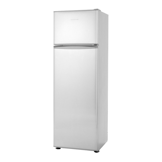
Fisher & Paykel E169T Service Manual
Electronic refrigerator freezer
Hide thumbs
Also See for E169T:
- Installation instructions and user manual (44 pages) ,
- User manual (36 pages) ,
- Installation instructions and user manual (36 pages)
Table of Contents
Advertisement
Advertisement
Table of Contents

Summary of Contents for Fisher & Paykel E169T
- Page 1 ELECTRONIC COMPACT SERIES REFRIGERATOR FREEZER Models E169T, E249T, E240B 517795...
- Page 2 MANUAL 517795 - AUGUST 2004 REPRINT: The specifications and servicing procedures outlined in this manual are subject to change without notice. The latest version is indicated by the reprint date and replaces any earlier editions. Fisher & Paykel Australia Pty Ltd Fisher &...
-
Page 3: Table Of Contents
CONTENTS INTRODUCTION ....................4 1.1 Electronics....................4 1.2 Product Specification..................4 1.2.1 Compressors..................4 1.2.2 Compressor Specification ..............4 1.3 Condenser Layout ..................5 ELECTRONICS ....................5 2.1 Control Module ...................5 2.2 Light Operation ...................5 2.3 Beeper......................5 2.4 Temperature Sensors.................5 2.5 Thermistor Sensors Resistance Table............6 2.6 FC Fan .......................6 2.7 Defrost Heater ....................6 2.8 Defrost Cycle ....................7 2.9 PC Heater....................7... -
Page 4: Introduction
INTRODUCTION The service manual covers the implementation the compact series electronic models E169T, E240B, E249T. Electronics Changes to the compacts are that an electronic module has replaced the defrost timer and relay. A variable resistor replaces the thermostat. With the introduction of the electronic module, some of the current functions of the product will also change. -
Page 5: Condenser Layout
Condenser Layout The new compressors have no oil cooler lines, therefore the re-routing of the condenser is as follows: Discharge line from the compressors runs directly to the condenser on the back panel. From the back panel it enters the LH side condenser, through the cross rail heater (if applicable) then into the RH condenser, then into the filter dryer. -
Page 6: Thermistor Sensors Resistance Table
Thermistor Sensors Resistance Table Temperature ( Resistance (K Ohms + 5%) -30.0 25.17 -25.0 19.43 -20.0 15.13 -15.0 11.88 -10.0 9.392 -5.0 7.481 6.000 4.844 10.0 3.935 15.0 3.217 20.0 2.644 25.0 2.186 30.0 1.817 35.0 1.518 40.0 1.274 45.0 1.075 50.0 0.9106... -
Page 7: Defrost Cycle
Defrost Cycle The defrost heater is controlled by the control module, which switches it via a relay. The defrost interval can vary from between 8 hours of compressor run time to 16 hours of compressor run time, depending on the duration time of the last defrost. When the control module switches the compressor off for a defrost, there is a 2 minute delay before the defrost heater is turned on. -
Page 8: Fault Codes
FAULT CODES If a fault should develop in the temperature measurement system, defrost system, temperature control variable resistor, or should the compressor fail to start, an audio fault alarm will sound when to P.C. door is opened. The alarm consists of a number of beeps emitted by the beeper located in the control module. -
Page 9: To Disable A Fault Alarm
Fault 9: 9 beeps Reason: The resistance of the PC sensor is outside the normal range (> 45K Ohms). Primary Action: Check sensor resistance. Check the sensor connection at the control module. Secondary Action: Replace the sensor. Fault 10: 10 beeps Reason: The resistance of the PC sensor is outside the normal range (<... -
Page 10: Service Procedures
SERVICE PROCEDURES Note: No work is to be carried out on the product while in a live situation. All components can be at a 230volt potential. The product is to be turned off and disconnected from the power source. Electrical Safety Checks Whenever any part of the electrical circuit is serviced or disturbed in the course of carrying out service adjustments or repair, it is essential that insulation and earth continuity tests are carried out using the appropriate test equipment. -
Page 11: Variable Resistor
• Replacement of the sensor is done by cutting the wiring to the old sensor as close to the sensor as possible. Strip each wire back far enough (about 10mm) to allow it to be soldered to the wiring of the new sensor. Strip each wire of the new sensor back a similar amount and slide some heat shrink sleaving over each wire. -
Page 13: Fault Finding
FAULT FINDING The following faults and probable cause/s have been listed with the assumption that all basic checks have been carried out. Example, product has power, door is closing correctly etc. Compressor Won’t Start • Check continuity of overload. If no continuity replace overload. •... -
Page 14: Fc Warm
FC Warm • Check setting of control. • Check door seal. • Check frost pattern of FC evaporator. If fully frosted, check defrost by forcing a defrost. • If defrost doesn’t work, check defrost sensor and/or defrost heater and fuses. •...


