Table of Contents
Advertisement
USER MANUAL
NI cRIO-905x
Embedded CompactRIO Controller with Real-Time Processor and
Reconfigurable FPGA
This document describes the features of the cRIO-905x and contains information about
mounting and operating the device.
In this document, the NI cRIO-9053, NI cRIO-9054, NI cRIO-9056, NI cRIO-9057 are
referred to collectively as cRIO-905x.
Advertisement
Table of Contents

Related Manuals for National Instruments NI cRIO-905x Series


Summary of Contents for National Instruments NI cRIO-905x Series
- Page 1 USER MANUAL NI cRIO-905x Embedded CompactRIO Controller with Real-Time Processor and Reconfigurable FPGA This document describes the features of the cRIO-905x and contains information about mounting and operating the device. In this document, the NI cRIO-9053, NI cRIO-9054, NI cRIO-9056, NI cRIO-9057 are referred to collectively as cRIO-905x.
-
Page 2: Table Of Contents
Contents Configuring the cRIO-905x...................... 2 Connecting the cRIO-905x to the Host Computer Using USB........3 Connecting the cRIO-905x to the Host Computer or Network Using Ethernet....4 Configuring Startup Options..................... 4 cRIO-905x Features........................6 Ports and Connectors......................6 Buttons..........................10 LEDs..........................11 Chassis Grounding Screw.................... -
Page 3: Connecting The Crio-905X To The Host Computer Using Usb
NI software in the correct order on the host computer as described in Installing Software on the Host Computer in the NI cRIO-905x Getting Started Guide. Select Configure and install software to this device. NI cRIO-905x User Manual | © National Instruments | 3... -
Page 4: Connecting The Crio-905X To The Host Computer Or Network Using Ethernet
Connecting the cRIO-905x to the Host Computer or Network Using Ethernet Complete the following steps to connect the cRIO-905x to a host computer or Ethernet network using the RJ-45 Gigabit Ethernet port 0. NI recommends using the RJ-45 Gigabit Ethernet port 0 for communication with deployed systems. Note If your controller has the RJ-45 Gigabit Ethernet port 1, you can configure that port in Measurement &... - Page 5 Info Code openssh for more information about SSH. LabVIEW Project Rebooting the cRIO-905x with this setting on enables you to add the Access target to a LabVIEW project. NI cRIO-905x User Manual | © National Instruments | 5...
-
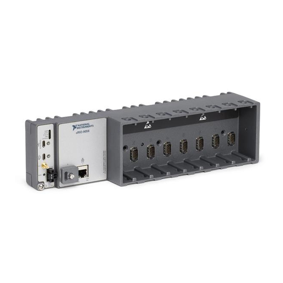
Page 6: Crio-905X Features
cRIO-905x Features Ports and Connectors Figure 1. cRIO-905x Ports and Connectors 1. USB 2.0 Type-C Device Port with Console Out 4. Power Connector 2. USB 3.1 Type-C Host Port 5. SD Association MicroSD Card Removable Storage 3. PFI 0 6. RJ-45 Gigabit Ethernet Ports (one or two, depending on the model) USB 2.0 Type-C Device Port with Console Out When operating a device, use this port to connect the cRIO-905x to a host PC. - Page 7 Choosing Your Programming Mode. Power Connector The cRIO-905x has a power connector to which you can connect a power supply. Table 4. Power Connector Pinout Pinout Description Power input Common NI cRIO-905x User Manual | © National Instruments | 7...
- Page 8 The cRIO-905x has reverse-voltage protection. The following NI power supplies and accessories are available for use with the cRIO-905x. Table 5. Power Supplies Accessory Part Number NI PS-10 Desktop Power Supply, 24 V DC, 5 A, 100-120/200-240 V AC 782698-01 Input NI PS-14 Industrial Power Supply, 24 to 28 V DC, 3.3 A, 100-240 V AC 783167-01...
- Page 9 The following NI Ethernet cables are available for use with the cRIO-905x. Table 9. RJ-45 Gigabit Ethernet Cables Cables Length Part Number 151733-02 CAT-5E Ethernet Cable, shielded 151733-05 10 m 151733-10 NI cRIO-905x User Manual | © National Instruments | 9...
-
Page 10: Buttons
Buttons Figure 2. cRIO-905x Buttons 1. RESET Button 2. CMOS Reset Button RESET Button Press the RESET button to reset the processor in the same manner as cycling power. Figure 3. Reset Button Behavior Press and hold RESET button for < 5 s Press and hold RESET button for ≥... -
Page 11: Leds
3. SD IN USE LED 6. Gigabit Ethernet LEDs POWER LED Indicators Table 10. POWER LED Indicators LED Pattern Indication Solid The cRIO-905x is powered on. The cRIO-905x is powered off. NI cRIO-905x User Manual | © National Instruments | 11... - Page 12 STATUS LED Indicators Table 11. STATUS LED Indicators LED Pattern Indication Blinks twice and The cRIO-905x is in safe mode. Software is not installed, which is the pauses factory default state, or software has been improperly installed on the cRIO-905x. An error can occur when an attempt to upgrade the software is interrupted.
- Page 13 Green Solid LAN link established Flashing Activity on LAN 10/100/1000 Yellow Solid 1,000 Mb/s data rate selected Green Solid 100 Mb/s data rate selected — 10 Mb/s data rate selected NI cRIO-905x User Manual | © National Instruments | 13...
-
Page 14: Chassis Grounding Screw
Chassis Grounding Screw Figure 5. cRIO-905x Chassis Grounding Screw 1. Chassis Grounding Screw Note For information about grounding the cRIO-905x, see Grounding the Controller in the NI cRIO-905x Getting Started Guide. Note For more information about ground connections, visit ni.com/info and enter the Info Code emcground... -
Page 15: Clock Routing
When programming C Series modules in Real-Time (NI-DAQmx) mode, the 80 MHz timebase can function as the source input to the 32-bit general-purpose counter/timers. The 80 MHz timebase is generated from the onboard oscillator. NI cRIO-905x User Manual | © National Instruments | 15... -
Page 16: Synchronization Across A Network
20 MHz and 100 kHz Timebases When programming C Series modules in Real-Time (NI-DAQmx) mode, the 20 MHz and 100 kHz timebases can be used to generate many of the analog input and analog output timing signals. These timebases can also function as the source input to the 32-bit general-purpose counter/timers. - Page 17 IEEE 802.1AS-2011 assumes all communication between devices is done on the OSI layer 2, while IEEE 1588-2008 can support various layer 2 and layer 3-4 communication methods. The IEEE 1588-2008 profile National Instruments implements on the cRIO-905x only supports layer 3-4 communication methods. Operating on the layer 2 yields better performance for the IEEE 802.1AS-2011.
-
Page 18: Battery
IEEE 1588 External Switch Requirements To take advantage of the network synchronization features of the cRIO-905x controllers, ensure that your network infrastructure meets certain requirements depending on which IEEE 1588 profile is implemented for your application: • IEEE 802.1AS-2011 support—Automatically enables timebase synchronization and enables the use of time-based triggers and timestamping between devices across the network. -
Page 19: Mounting The Controller
C Series module accuracy. Observe the following guidelines to mount the cRIO-905x in the reference mounting configuration. Figure 7. System Mounting Configuration NI cRIO-905x User Manual | © National Instruments | 19... -
Page 20: Alternative Mounting Configurations
Vertical mounting orientation. Mounting substrate options: • Mount the cRIO-905x directly to a metallic surface that is at least 1.6 mm (0.062 in.) thick and extends a minimum of 101.6 mm (4 in.) beyond all edges of the device. • Use the NI Panel Mounting Kit to mount the cRIO-905x to a metallic surface that is at least 1.6 mm (0.062 in.) thick and extends a minimum of 101.6 mm (4 in.) beyond all edges of the device. -
Page 21: Dimensions
1. Measure the ambient temperature here. Dimensions The following dimensional drawings apply to all cRIO-905x controllers. For detailed dimensional drawings and 3D models, visit ni.com/dimensions and search for the model number. NI cRIO-905x User Manual | © National Instruments | 21... - Page 22 Figure 11. cRIO-905x 4-slot Controller Front Dimensions 89.61 mm (3.528 in.) 221.40 mm (8.72 in.) Figure 12. cRIO-905x 8-slot Controller Front Dimensions 89.61 mm (3.528 in.) 328.64 mm (12.938 in.) 22 | ni.com | NI cRIO-905x User Manual...
-
Page 23: Front Mounting On A Flat Surface
Complete the following steps to front mount the cRIO-905x directly on a flat, rigid surface using the mounting holes. Note NI recommends surface mounting your system in environments with high shock and vibration. NI cRIO-905x User Manual | © National Instruments | 23... - Page 24 Figure 14. Front Mounting the 4-slot cRIO-905x Directly on a Flat Surface Figure 15. Front Mounting the 8-slot cRIO-905x Directly on a Flat Surface Prepare the surface for mounting the cRIO-905x using the Surface Mounting Dimensions. Align the cRIO-905x on the surface. Fasten the cRIO-905x to the surface using the M4 screws appropriate for the surface.
-
Page 25: Rear Mounting On A Flat Surface
Complete the following steps to rear mount the cRIO-905x directly on a flat, rigid surface using the mounting holes. Note NI recommends surface mounting your system in environments with high shock and vibration. NI cRIO-905x User Manual | © National Instruments | 25... - Page 26 Figure 18. Rear Mounting the 4-slot cRIO-905x Directly on a Flat Surface Figure 19. Rear Mounting the 8-slot cRIO-905x Directly on a Flat Surface 26 | ni.com | NI cRIO-905x User Manual...
-
Page 27: Mounting The Controller On A Panel
73.8 mm 120 mm 120 mm (2.91 in.) (4.72 in.) (4.72 in.) 328.6 mm (12.94 in.) Mounting the Controller on a Panel What to Use • cRIO-905x • Screwdriver, Phillips #2 NI cRIO-905x User Manual | © National Instruments | 27... - Page 28 • NI panel mounting kit for 4-slot controllers, 157253-01 – Panel mounting plate – M4 x 10 screws (x4) • NI panel mounting kit for 8-slot controllers, 157267-01 – Panel mounting plate – M4 x 10 screws (x6) What to Do Complete the following steps to mount the cRIO-905x on a panel.
- Page 29 Tighten the screws to a torque of 1.3 N · m (11.5 lb · in.). Fasten the panel mounting plate to the surface using the screwdriver and screws that are appropriate for the surface. The maximum screw size is M5 or number 10. NI cRIO-905x User Manual | © National Instruments | 29...
- Page 30 Panel Mounting Dimensions Figure 24. 4-slot cRIO-905x Panel Mounting Dimensions 217.7 mm (8.57 in.) 7.2 mm (0.29 in.) 199.4 mm (7.85 in.) 114.3 mm 138.9 mm (4.50 in.) (5.47 in.) 25.4 mm (1.00 in.) 108.8 mm (4.26 in.) Figure 25. 8-slot cRIO-905x Panel Mounting Dimensions 327 mm (12.88 in.) 7.2 mm (0.29 in.)
-
Page 31: Mounting On A Din Rail
M4 x 10 screws (x3) What to Do Complete the following steps to mount the cRIO-905x on a standard 35-mm DIN rail. Figure 26. Mounting the 4-slot cRIO-905x on a DIN Rail NI cRIO-905x User Manual | © National Instruments | 31... - Page 32 Figure 27. Mounting the 8-slot cRIO-905x on a DIN Rail Align the DIN rail clip with the mounting holes on the rear of the cRIO-905x. Fasten the DIN rail clip to the cRIO-905x using the screwdriver and M4 x 10 screws. Note You must use the screws provided with the NI DIN rail kit because they are the correct depth and thread for the DIN rail clip.
-
Page 33: Mounting On A Rack
Figure 29. Components of the NI Desktop Mount Kit 1. Desktop mounting brackets (x2) 2. Adapter bracket 3. M3 x 35 screws (x2) What to Do Complete the following steps to mount the cRIO-905x on a desktop. NI cRIO-905x User Manual | © National Instruments | 33... - Page 34 Figure 30. Mounting the 4-Slot cRIO-905x on a Desktop 34 | ni.com | NI cRIO-905x User Manual...
- Page 35 Align the desktop mounting brackets with the mounting holes at the end of the chassis and on the adapter bracket. Use a #2 Phillips screwdriver to tighten the captive screw on the end bracket. NI cRIO-905x User Manual | © National Instruments | 35...
- Page 36 Desktop Mounting Dimensions Figure 32. 4 Slot cRIO-905x Desktop Mounting Front Dimensions 22.9 mm 17.2 mm (1.14 in.) (0.68 in.) 39.1 mm (1.54 in.) Figure 33. 8 Slot cRIO-905x Desktop Mounting Front Dimensions 17.2 mm 22.9 mm (1.14 in.) (0.68 in.) 39.1 mm (1.54 in.) Figure 34.
-
Page 37: Choosing Your Programming Mode
FPGA. In either case, you use the Open FPGA VI Reference function in a LabVIEW Real-Time VI to access the FPGA VI or bitfile. NI cRIO-905x User Manual | © National Instruments | 37... -
Page 38: Analog Input With Ni-Daqmx
Table 15. Supported Programming Modes for Popular Tasks Task Real-Time Real-Time Scan FPGA Control rates up to 1 kHz ■ ■ Control rates between 1 kHz and 2.5 kHz ■ ■ ■ (application dependent) Control rates over 2.5 kHz ■ High-speed waveform acquisition ■... - Page 39 A sample consists of one reading from each channel in the AI task. Sample Clock signals the start of a sample of all analog input channels in the task. The sample clock can be generated from external or internal sources as shown in the figure below. NI cRIO-905x User Manual | © National Instruments | 39...
- Page 40 Figure 35. AI Sample Clock Timing Options Analog Comparison Event AI Sample Ctr n Internal Output Clock Sigma-Delta Module Internal Output Analog Comparison Sample Clock Event Timebase Programmable 80 MHz Timebase Clock Divider 20 MHz Timebase 13.1072 MHz Timebase 12.8 MHz Timebase 10 MHz Timebase 100 kHz Timebase Routing the Sample Clock to an Output Terminal...
- Page 41 When the reference trigger occurs, the cRIO controller continues to write samples to the buffer until the buffer contains the number of posttrigger samples desired. The figure below shows the final buffer. NI cRIO-905x User Manual | © National Instruments | 41...
- Page 42 Figure 36. Reference Trigger Final Buffer Reference Trigger Pretrigger Samples Posttrigger Samples Complete Buffer Using a Digital Source To use a reference trigger with a digital source, specify a source and a rising or falling edge. Either PFI or one of several internal signals on the cRIO controller can provide the source. Refer to the "Device Routing in MAX"...
- Page 43 When delta-sigma modules with different oversample clock frequencies are used in an analog input task, the AI Sample Clock Timebase can use any of the NI cRIO-905x User Manual | © National Instruments | 43...
-
Page 44: Analog Output With Ni-Daqmx
available frequencies; by default, the fastest available is used. The sample rate of all modules in the task is an integer divisor of the frequency of the AI Sample Clock Timebase. When one or more delta-sigma modules are in an analog input task, the delta-sigma modules also provide the signal used as the AI Sample Clock. - Page 45 In HWTSP mode, samples are acquired or generated continuously using hardware timing and no buffer. You must use the sample clock or change detection timing types. No other timing types are supported. NI cRIO-905x User Manual | © National Instruments | 45...
- Page 46 Use HWTSP mode if you need to know if a loop executes in a given amount of time, such as in a control application. Because there is no buffer, if you use HWTSP mode, ensure that reads or writes execute fast enough to keep up with hardware timing. If a read or write executes late, it returns a warning.
- Page 47 100 kHz Timebase Routing AO Sample Clock to an Output Terminal You can route AO Sample Clock to any output PFI terminal. AO Sample Clock is active high by default. NI cRIO-905x User Manual | © National Instruments | 47...
- Page 48 AO Sample Clock Timebase Signal The AO Sample Clock Timebase signal is divided down to provide a source for AO Sample Clock. AO Sample Clock Timebase can be generated from external or internal sources, and is not available as an output from the controller. Delta-Sigma Modules The oversample clock is used as the AO Sample Clock Timebase.
- Page 49 DAC code changes. You can build a lowpass deglitching filter to remove some of these glitches, depending on the frequency and nature of the output signal. Go to ni.com/support more information about minimizing glitches. NI cRIO-905x User Manual | © National Instruments | 49...
-
Page 50: Digital Input/Output With Ni-Daqmx
Getting Started with AO Applications in Software You can use the cRIO controller in the following analog output applications: • Single-point (on-demand) generation • Hardware-Timed Single Point generation • Finite generation • Continuous generation • Waveform generation For more information about programming analog output applications and triggers in software, refer to NI-DAQmx Help or to the LabVIEW Help. - Page 51 Refer to the DI Start Trigger Signal, DI Reference Trigger Signal, and DI Pause Trigger Signal sections in Digital Input Timing Signals for more information about the digital input trigger signals. NI cRIO-905x User Manual | © National Instruments | 51...
- Page 52 Digital Input Timing Signals The cRIO controller features the following digital input timing signals: • DI Sample Clock Signal* • DI Sample Clock Timebase Signal • DI Start Trigger Signal* • DI Reference Trigger Signal* • DI Pause Trigger Signal* Signals with an * support digital filtering.
- Page 53 To use the Start Trigger signal with a time source, configure a specific time in NI-DAQmx. Refer to the "Timestamps" and "Time Triggering" topics in the NI-DAQmx Help for more information on accessing time-based features in the NI-DAQmx API. NI cRIO-905x User Manual | © National Instruments | 53...
- Page 54 Using a Digital Source To use DI Start Trigger with a digital source, specify a source and a rising or falling edge. Use the following signals as the source: • Any PFI terminal • Counter n Internal Output The source also can be one of several other internal signals on the cRIO controller. Refer to the "Device Routing in MAX"...
- Page 55 Tp is a nominal value; the accuracy of the controller timebase and I/O distortion will affect this value. NI cRIO-905x User Manual | © National Instruments | 55...
- Page 56 Figure 42. Filter Example Digital Input P0.x Filter Clock Filtered Input Getting Started with DI Applications in Software You can use the cRIO controller in the following digital input applications: • Single-point acquisition • Hardware-Timed Single Point acquisition • Finite acquisition •...
- Page 57 Because there is no buffer, if you use HWTSP mode, ensure that reads or writes execute fast enough to keep up with hardware timing. If a read or write executes late, it returns a warning. NI cRIO-905x User Manual | © National Instruments | 57...
- Page 58 Buffered Digital Output A buffer is a temporary storage in computer memory for generated samples. In a buffered generation, data is moved from a host buffer to the cRIO controller onboard FIFO before it is written to the C Series module(s). One property of buffered I/O operations is sample mode.
- Page 59 The DO Sample Clock Timebase signal is divided down to provide a source for DO Sample Clock. DO Sample Clock Timebase can be generated from external or internal sources and is not available as an output from the controller. NI cRIO-905x User Manual | © National Instruments | 59...
- Page 60 DO Start Trigger Signal Use the DO Start Trigger signal to initiate a waveform generation. If you do not use triggers, you can begin a generation with a software command. If you are using an internal sample clock, you can specify a delay from the start trigger to the first sample. For more information, refer to the NI-DAQmx Help.
- Page 61 For this reason, you must reserve the task in advance through the DAQmx Control Task before any task has started. If another task or route NI cRIO-905x User Manual | © National Instruments | 61...
-
Page 62: Pfi With Ni-Daqmx
is actively using the module, to avoid interfering with the other task, NI-DAQmx generates an error instead of sending the line configuration command. During the line configuration command, the output lines are maintained without glitching. PFI with NI-DAQmx You can configure channels of a parallel digital module as Programmable Function Interface (PFI) terminals. -
Page 63: Counters With Ni-Daqmx
(Embedded Ctrn) for use in what are traditionally two-counter measurements and generations. The embedded counters cannot be programmed independent of the main counter; signals from the embedded counters are not routable. NI cRIO-905x User Manual | © National Instruments | 63... - Page 64 Counter Timing Engine Unlike analog input, analog output, digital input, and digital output, the cRIO controller counters do not have the ability to divide down a timebase to produce an internal counter sample clock. For sample clocked operations, an external signal must be provided to supply a clock source.
- Page 65 When using a pause trigger, the pause trigger source is routed to the Counter n Gate signal input of the counter. NI cRIO-905x User Manual | © National Instruments | 65...
- Page 66 Default Counter/Timer Routing Counter/timer signals are available to parallel digital I/O C Series modules. To determine the signal routing options for modules installed in your system, refer to the Device Routes tab in MAX. You can use these defaults or select other sources and destinations for the counter/timer signals in NI-DAQmx.
- Page 67 Source signal, and counts on the following rising edge of the source, as shown in the figure below. Figure 50. External or Internal Source Less than 20 MHz Source Synchronize Delayed Source Count NI cRIO-905x User Manual | © National Instruments | 67...
-
Page 68: Counter Input Applications
Counter Input Applications The following sections list the various counter input applications available on the cRIO controller: • Counting Edges • Pulse-Width Measurement • Pulse Measurement • Semi-Period Measurement • Frequency Measurement • Period Measurement • Position Measurement • Two-Signal Edge-Separation Measurement Counting Edges In edge counting applications, the counter counts edges on its Source after the counter is armed. - Page 69 • Count up when the Counter 0 B input is high; count down when it is low For information about connecting counter signals, refer to the Default Counter/Timer Routing section. NI cRIO-905x User Manual | © National Instruments | 69...
- Page 70 Pulse-Width Measurement In pulse-width measurements, the counter measures the width of a pulse on its Gate input signal. You can configure the counter to measure the width of high pulses or low pulses on the Gate signal. You can route an internal or external periodic clock signal (with a known period) to the Source input of the counter.
- Page 71 Sample Clock Buffer Note If a pulse does not occur between sample clocks, an overrun error occurs. For information about connecting counter signals, refer to the Default Counter/Timer Routing section. NI cRIO-905x User Manual | © National Instruments | 71...
- Page 72 Pulse Measurement In pulse measurements, the counter measures the high and low time of a pulse on its Gate input signal after the counter is armed. A pulse is defined in terms of its high and low time, high and low ticks or frequency and duty cycle. This is similar to the pulse-width measurement, except that the inactive pulse is measured as well.
- Page 73 In semi-period measurements, the counter measures a semi-period on its Gate input signal after the counter is armed. A semi-period is the time between any two consecutive edges on the Gate input. NI cRIO-905x User Manual | © National Instruments | 73...
- Page 74 You can route an internal or external periodic clock signal (with a known period) to the Source input of the counter. The counter counts the number of rising (or falling) edges occurring on the Source input between two edges of the Gate signal. You can calculate the semi-period of the Gate input by multiplying the period of the Source signal by the number of edges returned by the counter.
- Page 75 The following figure illustrates this method. Figure 61. Low Frequency with One Counter Interval Measured Gate … … Source Single Period Period of fx = Measurement Frequency of fx = NI cRIO-905x User Manual | © National Instruments | 75...
- Page 76 High Frequency with Two Counters For high frequency measurements with two counters, you measure one pulse of a known width using your signal and derive the frequency of your signal from the result. Note Counter 0 is always paired with Counter 1. Counter 2 is always paired with Counter 3.
- Page 77 T2 is the number of ticks counted of the known timebase as shown in the following figure. The frequency measured is fx = fk * (T1/T2). NI cRIO-905x User Manual | © National Instruments | 77...
- Page 78 Figure 64. Sample Clocked Buffered Frequency Measurement (Averaging) Counter Armed Gate (fx) Source (fk) Sample Clock T1 T2 T1 T2 T1 T2 Buffer 2 10 2 10 When CI.Freq.EnableAveraging is set to False, the frequency measurement returns the frequency of the pulse just before the sample clock. This single measurement is a single frequency measurement and is not an average between clocks as shown in the following figure.
- Page 79 × − 1 Max. error % Note Accuracy equations do not take clock stability into account. Refer to the specifications document for your chassis for information about clock stability. NI cRIO-905x User Manual | © National Instruments | 79...
- Page 80 Which Method Is Best? This depends on the frequency to be measured, the rate at which you want to monitor the frequency and the accuracy you desire. Take for example, measuring a 50 kHz signal. Assuming that the measurement times for the sample clocked (with averaging) and two counter frequency measurements are configured the same, the following table summarizes the results.
- Page 81 Range Number of counters 1 or 2 used Number of measurements returned Measures high Good Poor Good Good frequency signals accurately Measures low frequency Good Good Good Poor signals accurately NI cRIO-905x User Manual | © National Instruments | 81...
- Page 82 For information about connecting counter signals, refer to the Default Counter/Timer Routing section. Period Measurement In period measurements, the counter measures a period on its Gate input signal after the counter is armed. You can configure the counter to measure the period between two rising edges or two falling edges of the Gate input signal.
- Page 83 Thus, when the channel B goes low to enter the reload phase, the increment occurs first. The reload occurs within one maximum timebase period after the NI cRIO-905x User Manual | © National Instruments | 83...
- Page 84 reload phase becomes true. After the reload occurs, the counter continues to count as before. The figure below illustrates channel Z reload with X4 decoding. Figure 69. Channel Z Reload with X4 Decoding Ch A Ch B Ch Z Max Timebase Counter Value A = 0 B = 0...
- Page 85 Aux signal. The counter then stores the count in the FIFO and ignores other edges on its inputs. Software then reads the stored count. The following figure shows an example of a single two-signal edge-separation measurement. NI cRIO-905x User Manual | © National Instruments | 85...
- Page 86 Figure 72. Single Two-Signal Edge-Separation Measurement Counter Armed Measured Interval GATE SOURCE Counter Value Latched Value Implicit Buffered Two-Signal Edge-Separation Measurement Implicit buffered and single two-signal edge-separation measurements are similar, but implicit buffered measurement measures multiple intervals. The counter counts the number of rising (or falling) edges on the Source input occurring between an active edge of the Gate signal and an active edge of the Aux signal.
-
Page 87: Counter Output Applications
You can specify a delay from when the counter is armed to the beginning of the pulse. The delay is measured in terms of a number of active edges of the Source input. NI cRIO-905x User Manual | © National Instruments | 87... - Page 88 You can specify a pulse width. The pulse width is also measured in terms of a number of active edges of the Source input. You also can specify the active edge of the Source input (rising or falling). The following figure shows a generation of a pulse with a pulse delay of four and a pulse width of three (using the rising edge of Source).
- Page 89 The figure below shows a generation of two pulses with a pulse delay of five and a pulse width of three (using the rising edge of Source) with CO.EnableInitalDelayOnRetrigger set to the default True. NI cRIO-905x User Manual | © National Instruments | 89...
- Page 90 Figure 78. Retriggerable Single Pulse Generation with Initial Delay on Retrigger Counter Load Values 4 3 2 1 0 2 1 0 4 3 2 1 0 2 1 0 GATE (Start Trigger) SOURCE The figure below shows the same pulse train with CO.EnableInitalDelayOnRetrigger set to the default False.
- Page 91 (pulse specifications) you write determines the number of pulses generated. All points are generated back to back to create a user defined pulse train. The following table and figure detail a finite implicit generation of three samples. NI cRIO-905x User Manual | © National Instruments | 91...
- Page 92 Table 22. Finite Implicit Buffered Pulse Train Generation Sample Idle Ticks Active Ticks Figure 81. Finite Implicit Buffered Pulse Train Generation SOURCE Counter Armed Continuous Buffered Implicit Pulse Train Generation This function generates a continuous train of pulses with variable idle and active times. Instead of generating a set number of data samples and stopping, a continuous generation continues until you stop the operation.
- Page 93 The frequency generator can output a square wave at many different frequencies. The frequency generator is independent of the four general-purpose 32-bit counter/timer modules on the cRIO controller. The following figure shows a block diagram of the frequency generator. NI cRIO-905x User Manual | © National Instruments | 93...
- Page 94 Figure 83. Frequency Generator Block Diagram Frequency Output ÷ 20 MHz Timebase Timebase Frequency Generator FREQ OUT 100 kHz Timebase Divisor (1–16) The frequency generator generates the Frequency Output signal. The Frequency Output signal is the Frequency Output Timebase divided by a number you select from 1 to 16. The Frequency Output Timebase can be either the 20 MHz Timebase, the 20 MHz Timebase divided by 2, or the 100 kHz Timebase.
-
Page 95: Counter Timing Signals
Counter n Aux Signal • Counter n A, Counter n B, and Counter n Z Signals • Counter n Up_Down Signal • Counter n HW Arm Signal • Counter n Sample Clock Signal NI cRIO-905x User Manual | © National Instruments | 95... - Page 96 • Counter n Internal Output and Counter n TC Signals • Frequency Output Signal In this section, n refers to the cRIO controller Counter 0, 1, 2, or 3. For example, Counter n Source refers to four signals—Counter 0 Source (the source input to Counter 0), Counter 1 Source (the source input to Counter 1), Counter 2 Source (the source input to Counter 2), or Counter 3 Source (the source input to Counter 3).
- Page 97 Each counter has independent input selectors for the Counter n Aux signal. Any of the following signals can be routed to the Counter n Aux input: • Any PFI terminal • AI Reference Trigger • AI Start Trigger NI cRIO-905x User Manual | © National Instruments | 97...
- Page 98 • Analog Comparison Event • Change Detection Event In addition, a counter’s Internal Output, Gate or Source can be routed to a different counter’s Aux. A counter’s own gate can also be routed to its Aux input. Some of these options may not be available in some driver software. Refer to the "Device Routing in MAX"...
- Page 99 Routing Counter n Sample Clock to an Output Terminal You can route Counter n Sample Clock out to any PFI terminal. The PFI circuitry inverts the polarity of Counter n Sample Clock before driving the PFI terminal. NI cRIO-905x User Manual | © National Instruments | 99...
-
Page 100: Worldwide Support And Services
NI trademarks. Other product and company names mentioned herein are trademarks or trade names of their respective companies. For patents covering NI products/technology, refer to the appropriate location: Help»Patents in your software, the file on your media, or the National Instruments Patent Notice at . You can find patents.txt ni.com/patents...