Table of Contents
Advertisement
Installation Guide
English
Freestanding
Water Optimizer
Freestanding Purifier·Dispenser
Model: KM1000(B)
Customer Assistance
1-844-374-6576
www.kenmore.com
Kenmore and the Kenmore logo are the registered
trademarks of KCD IP, LLC and/or Sears Brands, LLC
and are used under license by Drinkpod, LLC
All Rights Reserved.
Advertisement
Table of Contents

Related Manuals for Kenmore KM1000


Summary of Contents for Kenmore KM1000
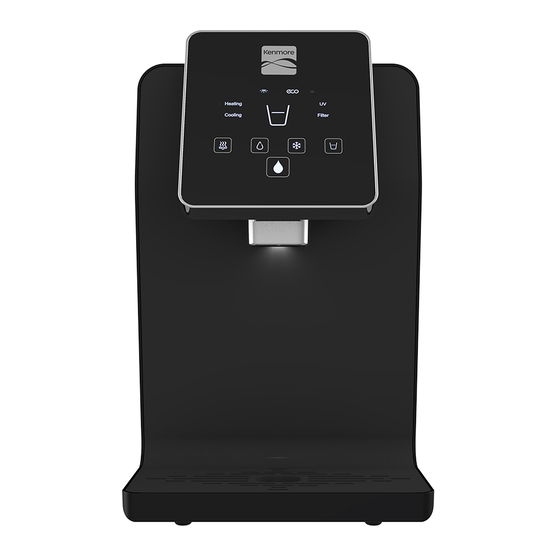
- Page 1 English Freestanding Water Optimizer Freestanding Purifier·Dispenser Model: KM1000(B) Customer Assistance 1-844-374-6576 www.kenmore.com Kenmore and the Kenmore logo are the registered trademarks of KCD IP, LLC and/or Sears Brands, LLC and are used under license by Drinkpod, LLC All Rights Reserved.
-
Page 2: Table Of Contents
Table Of Contents IMPORTANT SAFETY INSTRUCTIONS GETTING STARTED Installation Components List Configuration & Location Preparation Tapping Water Source 2-11 INSTALLING YOUR WATER OPTIMIZER 2-11 Running Water Source Line 2-23 Flushing Your Filters 2-26 Connecting Accessory Appliances 2-33 Connecting Water Optimizer 2-43 Installing Filters 2-46... -
Page 3: Important Safety Instructions
Ensure the power cord is always unplugged before performing any maintenance, troubleshooting, or filter upgrades. Only use Kenmore or Drinkpod accessories and filters to avoid causing damage and voiding product warranty. For all service and support related issues, please contact Drinkpod. -
Page 4: Getting Started
Getting Started Installation Components List Included with your Water Optimizer are a broad assortment of installation accessories. Do not get overwhelmed. While it is highly unlikely that you will require all of them, working with anything connected to your homes water system can be the wild west, and plumbers are rogue gunslingers. - Page 5 Getting Started 25’ Coil of 1/4 in. White PP Tubing 1/4 in. Compression To Quick Connect Adapter (x6) 1/4 in. Quick Connect Shutoff Valve (x2) 1/4 in. Brass Compression Union 1/4 in. Brass Compression Tee 3/8 in. Sink Adapter Valve (1/4 in. Custom x 3/8 in. Male x 3/8 in. Female x Compression Steel Angle Stop Valve Adapter) Filter Flushing Attachment Expansion Filter Mounting Bracket...
-
Page 6: Configuration & Location
Getting Started Before we proceed with your installation, we must first identify how and where to install your new Water Optimizer. This will be the most complicated part of the installation process. Don’t be intimidated! We’ve worked hard to write the best set of instructions you’ll ever read. - Page 7 Getting Started Accessory Water Line Configurations Example Installation #1.1 Accessory Water Line Source source BEFORE Accessory Water Source (Ice Maker) acc. AFTER Accessory Water Source Water Optimizer (Ice Maker) (Ice Maker Connection) Diagram 2.1.1-A Accessory Water Line Source (Not Connected, No Accessory Appliances) Example Installation #1.2 Accessory Water Line Source - 1x Accessory Appliance source...
- Page 8 Getting Started Example Installation #1.3 Accessory Water Line Source - 2x Accessory Appliances source BEFORE Accessory Refrigerator Water Source (Ice Maker Connection) acc. AFTER Accessory Water Refrigerator Water Source Optimizer (Ice Maker Connection) Coffee Maker (Input Port) Diagram 2.1.1-C Accessory Water Line Source (Connected, 2 Accessory Appliances) Sink Faucet Cold Water Line Configurations Example Installation #2.1 Sink Faucet Cold Water Line Source...
- Page 9 Getting Started Example Installation #2.2 Sink Faucet Cold Water Line Source - 1x Accessory Appliance source BEFORE Sink Faucet Water Source Accessory Refrigerator (Under Kitchen Sink) Water Source (Ice Maker Connection) acc. AFTER Sink Faucet Water Source Water Refrigerator (Under Kitchen Sink) Optimizer (Ice Maker Connection) Diagram 2.1.2-B Faucet Cold Water Line Source (1 Accessory Appliance)
- Page 10 Getting Started Alternative Configuration Example Installation #3 Accessory Water Line Source - Low Pressure Alternative source BEFORE Accessory Refrigerator Water Source (Ice Maker Connection) acc. AFTER Water Optimizer Accessory Refrigerator Water Source (Ice Maker Connection) Diagram 2.1.3 Low Water Pressure Alternative (Shared in Parallel) 4.
-
Page 11: Preparation
Getting Started Preparation Before we start tapping your water source, there are a few items you need to grab that weren’t included in your installation kit. • Sharp Knife or Scissors • Pliers, or Adjustable Wrench, or Open-End 7/16 in. Wrench (all installations), 1/2 in. - Page 12 Getting Started Cold Water Line” on page 2-16. Getting Started 2-10...
-
Page 13: Tapping Water Source
Installing Your Water Optimizer Tapping Water Source Option A: Tapping Accessory Water Line source In this section, you will require 1/4 in. White PP Tubing, and may also need Adapter, and pliers, or an adjustable wrench or 1/4 in. Compression To Quick Connect 1/2 in. - Page 14 Installing Your Water Optimizer Diagram 2.3(A).4-A Wall Mounted Accessory Water Line Source Diagram 2.3(A).4-B Floor Mounted Accessory Water Line Source Installing Your Water Optimizer 2-12...
- Page 15 Installing Your Water Optimizer Diagram 2.3(A).4-C Unmounted/Free Accessory Water Line Source 5. Turn the valve handle clockwise until it stops to shut off water flow. Diagram 2.3(A).5-A/B Closing Source Valve Installing Your Water Optimizer 2-13...
- Page 16 Installing Your Water Optimizer 6. Now, use pliers, adjustable or 1/2 in. wrench, to disconnect the appliance water line from the source shutoff valve. If you’re unsure how to disconnect the water line, see “Appendix B - Component Connections” on page 2-60.
- Page 17 Installing Your Water Optimizer Valve. Diagram 2.3(A).7 Connect Compression-To-Quick Connect Adapter 8. Connect one end of 1/4 in. White PP Tubing 1/4 in. Compression To Quick Connect Adapter. Diagram 2.3(A).8 Connect Tubing To Water Source 9. Congratulations! You’ve just completed the second most difficult part of your installation. Now jump ahead to “Running Water Source Line Step #4”...
- Page 18 Installing Your Water Optimizer Option B: Tapping Faucet Cold Water Line source 1. For this section, you will need 3/8 in. Sink Adapter Valve, as well as pliers, a crescent wrench, or 7/16 in. and 11/16 in. open ended wrenches (see “Preparation”...
- Page 19 Installing Your Water Optimizer KS-J: Right Drain KS-E KS-H KS-B KS-I KS-A KS-C KS-G KS-J KS-D KS-F Diagram 2.3(B).2 Under Sink Reference Diagram 3. We will be tapping the cold water line, which is typically on the right, but its always smart to confirm the plumber didn’t take any ‘creative liberties’...
- Page 20 Installing Your Water Optimizer Diagram 2.3(B).3 Turn On Cold Water In Sink KS-F 4. Now turn the handle of clockwise until it won’t turn Cold Water Shutoff Valve any further. If your faucet stops pouring water, we’ve confirmed this is your cold water shutoff.
- Page 21 Installing Your Water Optimizer connection is almost certainly a ½ in. (Nominal/NPT) fitting. If you have a 15/16 in. and a 1 in. wrench, you can check to confirm by attempting to loosen the connection (there is 1/16 in. range of variance between different plumbing fittings). IF THAT DOESN’T FIT, you have an extremely rare setup, and should contact a plumber.
- Page 22 Installing Your Water Optimizer Diagram 2.3(B).6 Attach Sink Adapter Valve To Cold Water Shutoff Valve KS-G 7. Now using your hand, screw the (female) end of Cold Water Feed Line onto the top (male) end of 3/8 in. Sink Adapter Valve, and use wrench to tighten using medium force.
- Page 23 Installing Your Water Optimizer KS-F open the flow on by repeating “Step 4” on page Cold Water Shutoff Valve 1-2. Water should pour from faucet, and nothing should be no leaking below. If there KS-H are leaks, tighten connections with wrench, then turn off faucet and proceed.
- Page 24 Installing Your Water Optimizer 11. Now stretch the same end of 1/4 in. White PP Tubing over the ‘nipple’ of 3/8 in. Sink Adapter Valve’s side connection until it butts up against the threads. This may require pressing very firmly and twisting back and forth. Diagram 2.3(B).11 - Stretch/Press Tubing Over Sink Adapter Valve Compression Nipple 12.
-
Page 25: Running Water Source Line
Installing Your Water Optimizer Running Water Source Line It’s time to run your water line (tubing) from your water source to where your Optimizer will be place. For this section, you will require 1. Uncoil and run 1/4 in. White PP Tubing, from where its connected (to your water source) to wherever you intend to locate your Optimizer. - Page 26 Installing Your Water Optimizer Diagram 2.4.4 Connect Tubing To Shutoff Valve 5. Make sure the valve handle is closed by turning it clockwise as far as it will go. When closed, the handle extends out perpendicularly to the length of the shutoff valve. Diagram 2.4.5 Ensure Valve Is Closed 6.
- Page 27 Installing Your Water Optimizer Diagram 2.4.6-A - Open Icemaker Source Diagram 2.4.6-B - Open Sink Source 7. If there are no leaks, you’re doing great, and are ready to proceed to the next stage, ”Flushing Your Filters” on page 2-26. If there is a leak, shut off the water flow. Review the connections and “Steps 3 - 5”...
-
Page 28: Flushing Your Filters
Installing Your Water Optimizer Flushing Your Filters Certain types of filters require flushing prior to use. This is important for both the filters lifespan, and the long term lifespan of your Water Optimizer. Additionally, replacements for these types of filters should be flushed each time one is replaced, prior to installing. - Page 29 Installing Your Water Optimizer Diagram 2.5.2 Insert Tubing Into Quick Connect Input Port 3. Now pull backwards on tubing, away from attachment, extending the QC sleeve, and ensuring the connections is ‘locked’ . Diagram 2.5.3 Pull & Lock Quick Connect Connection 4.
- Page 30 Installing Your Water Optimizer Diagram 2.5.4 OPTIONAL Connect Drain Line To Flushing Accessory ‘OUT’ Port 5. Follow the same steps to connect the open end of the (not the IN line line)from your and connect it to the open port on your Filter Flushing Attachment, 1/4 in.
- Page 31 Installing Your Water Optimizer Diagram 2.5.6 Connect REDOX Filter To Filter Flushing Accessory 7. Place the filter and in your sink or container (for Filter Flushing Attachment draining water). Ensure the labeled is pointed to direct water down - so the ‘OUT’...
- Page 32 Installing Your Water Optimizer Diagram 2.5.8 Open Quick Connect Valve 9. Flush the filter for a total of 2 minutes. Then shut off the water flow, and disconnect the filter. Be careful to set the filter down upright on a solid surface, to avoid spilling the water remaining in the filter.
- Page 33 Installing Your Water Optimizer Diagram 2.5.10 Connect & Flush Polishing Filter 11. Now push the tubing (running from Filter Flushing Attachment back into the valve as far as possible. Then, 1/4 in. Quick Connect Shutoff Valve while using your thumb to keep the QC sleeve fully depressed, gently pull the tubing out of the port.
- Page 34 Installing Your Water Optimizer 13. Now, if you plan to connect any other appliances to your Optimizer (i.e. refrigerator or coffeemaker) proceed to “Connecting Accessory Appliances” on page 2-33. Otherwise, proceed to “Connecting Water Optimizer” on page 2-43. Installing Your Water Optimizer 2-32...
-
Page 35: Connecting Accessory Appliances
Installing Your Water Optimizer Connecting Accessory Appliances Alright! It’s time to connect any additional appliances you want your new Water Optimizer to provide purified water to. These can include refrigerators (ice maker/water dispenser), stand alone ice makers, and coffee, espresso, or barista machines that support an inline water feed. - Page 36 Installing Your Water Optimizer If your appliance is equipped with a or(threaded Male Compression Port connection like a hollow bolt, can be metal or plastic). Diagram 2.6.0-C - Male Compression Port Example If your appliance is equipped with either a Female Compression Port Hose (threaded connection like an attached nut, can be metal or plastic).
- Page 37 Installing Your Water Optimizer CONFIGURATION OF ACCESSORIES If you are only connecting 1 Accessory Appliance. acc. If you are connecting 2 Accessory Appliances. acc. If you have low water pressure and require the Parallel Configuration (see acc. below). For safety reasons, we recommend powering off and unplug the appliances you want to connect.
- Page 38 Installing Your Water Optimizer If your low water pressure requires a Parallel Configuration, you will be acc. connecting your Optimizer and refrigerator (or whatever other appliance was originally connected to your water source) first to Tee, and then connecting this to the water source. You can 1/4 in.
- Page 39 Installing Your Water Optimizer Diagram 2.6.3-A - Screw Compression To Quick Connect Adapter Onto Port or Hose 1 Accessory Appliance Configurations, you will need to run a section of acc. 1/4 in. White PP Tubing from your Accessory Appliance, directly to where you plan to locate your Water Optimizer (unless the appliance alread has an integrated hose you plan to use instead).
- Page 40 Installing Your Water Optimizer To extend Quick Connect Tubing, use 1/4 in. Brass Compression Union and 2x 1/4 in. Compression To Quick Connect Adapters to connect the tubing running from your appliance to a section of Tubing, as 1/4 in. White PP shown below.
- Page 41 Installing Your Water Optimizer Diagram 2.6.4-B - Extending Female Compression Hose or Port With Brass Union Merging This is where we will be connecting both appliances to acc. acc. 1/4 in. Brass Compression Tee, then running a single merged line to the final destination.
- Page 42 Installing Your Water Optimizer power on your accessory appliance. To connect to the Quick Connect Tubing 1/4 in. Brass Compression Tee, unscrew the compression nut (from the port specified in the applicable diagram below), and thread the Quick Connect Tubing through it.
- Page 43 Installing Your Water Optimizer Diagram 2.6.5-B - Merging Connections to Brass Compression Tee For Parallel Configuration Final Check 4. Your Acc. Appliances should be connected to 1/4 in. Brass Compression Tee, and there should be a section of 1/4 in. White PP Tubing running from there to where your Water Optimizer will be located, with attached to the other end.
- Page 44 Installing Your Water Optimizer ACCESSORY ACCESSORY APPLIANCE #1 APPLIANCE #2 ADAPTER ADAPTER if necessary if necessary TUBING TUBING BRASS if necessary if necessary COMPRESSION SHUTOFF VALVE Location for Water Optimizer Diagram 2.6.6-A - Reference To Final Check For 2 Accessory Appliance Configuration Location for Water Optimizer ACCESSORY...
-
Page 45: Connecting Water Optimizer
Installing Your Water Optimizer Connecting Water Optimizer Congratulations! You are now close enough to the end that you should be able to taste it. This is the second easiest of the final stages. You should either have one or two water lines that end in 1/4 in. - Page 46 Installing Your Water Optimizer 4. Next, remove the Input Port Plug from Source Input Port using the standard quick connect detach method, as shown below (but with appliance port and plug, rather than shutoff valve and tubing). Diagram 2.7.4 - How To Detach Quick Connect Tubing 5.
- Page 47 Installing Your Water Optimizer 6. If you’ve connected accessory appliances, use the same method from Step #4 remove from on the back of your Acc. Output Port Plug Accessory Output Port Water Optimizer. If you don’t have any accessory appliances, proceed to “Installing Filters”...
-
Page 48: Installing Filters
Installing Your Water Optimizer Installing Filters Please note, only the INTERNAL filter (ULTRA+3) is required for the appliance to function. However, this special edition comes with an additional EXTERNAL filter (Particle) that will, in many cases, extend your primary filters life. We recommend installing it from the beginning, but can be connected later, as necessary. -
Page 49: Optional - Expanding Purification Capabilities
Installing Your Water Optimizer 3. To install, hold the ULTRA+3 Hybrid Filter in your hand so that its name on the label is rotated roughly 90 degrees counterclockwise. This (or rotated 180 degrees further) is the direction each filter should be rotated before beginning to insert it into the mounting bracket. - Page 50 Installing Your Water Optimizer Diagram 2.8.7 - Insert Expansion Filter Mounting Bracket 8. Pivot the bracket back so that the lower ‘arms’ insert into the lower mounting slots. Diagram 2.8.8 - Pivot Expansion Filter Mounting Bracket Back/Down 9. Slide the bracket down till it sits firmly in place. You may need to lift the tab on the lower end of the bracket outward to allow the bracket to slide all of the way down.
- Page 51 Installing Your Water Optimizer Diagram 2.8.9 - Slide Expansion Filter Mounting Bracket Firmly Into Place 10. Next, slide part all the way down into part Expansion Filter EZ-Twist Mount Expansion Filter Mounting Bracket. Diagram 2.8.10 - Slide Expansion Filter EZ-twist Mount Into Bracket 11.
- Page 52 Installing Your Water Optimizer Diagram 2.8.11 - Connect Expansion Filter Appliance Line To Mount 12. Remove the plug from the at the back of your Optimizer. Source/Input Port Diagram 2.8.12 - Remove Plug From Source/Input Port 13. Now, connect the other end of Expansion Filter Appliance Line into the RIGHT...
- Page 53 Installing Your Water Optimizer Diagram 2.8.13 - Connect Expansion Filter Appliance Line To Water Optimizer Input 14. Connect the end of part Expansion Filter Source Line with the right-angle fitting into the LEFT port of Expansion Filter EZ-Twist Mount (labeled IN).
- Page 54 Installing Your Water Optimizer same steps as the internal filter. Diagram 2.8.15 - Inser Particle Filter Into Mount 16. Proceed to “Enabling Water Flow” on page 2-52. You’re almost finished! Diagram 2.8.16 - Expansion Filter Assembly Properly Connected Installing Your Water Optimizer 2-52...
-
Page 55: Enabling Water Flow
Installing Your Water Optimizer Enabling Water Flow This is the second to last stage of installation. In this stage, we will enable water flow at each shutoff valve, one at a time to ensure there are no leaks. 1. If it’s not already open, start by opening your Water Source Valve (the valve on your existing water source we first shut off). - Page 56 Installing Your Water Optimizer Diagram 2.8.4 - Open Shutoff Valve 5. You should hear water running and filling the Optimizer’s tanks. Check for leaks, and wait until the sound of water running stops. 6. Once the Optimizer is filled, plug it in, but do not flip on the power switches yet. 7.
- Page 57 Installing Your Water Optimizer appliances for leaks. Diagram 2.8.11 - Open Shutoff Valve On Accessory Line 11. Once you here the water stop flowing, you can plug your accessory appliances back in and power them on. If possible, flush water through each for 1 minute. 12.
-
Page 58: Appendices
APPENDICES Appendix A - Water Sources Accessory Water Line Source - Wall Mounted Shutoff water by turning valve handle clockwise (usually 90 degrees). Disconnect water line by unscrewing compression bolt counterclockwise. Connect new water line with either... Valve Handle Valve Hose Compression Nut Water Line Hose APPENDICES 2-56... - Page 59 APPENDICES Accessory Water Line Source - Floor Mounted 1. Shutoff water by turning valve handle clockwise (usually 90 degrees). 2. Disconnect water line by unscrewing compression bolt counterclockwise. 3. Connect new water line with either... Hose Compression Nut Water Line Hose Valve Handle Valve APPENDICES 2-57...
- Page 60 APPENDICES Accessory Water Line Source - Unmounted 1. Shutoff water by turning valve handle clockwise (usually 90 degrees). 2. Disconnect water line by unscrewing compression bolt counterclockwise. Hose Compression Nut Water Line Hose Valve Handle Valve Feed Line APPENDICES 2-58...
- Page 61 APPENDICES Faucet Cold Water Line Source 1. Shutoff water by turning KS-F valve handle clockwise until it stops. 2. Disconnect water line by unscrewing the compression bolt on the end KS-G connected to KS-F counterclockwise. KS-E KS-H KS-B KS-I KS-A KS-C KS-G KS-J...
- Page 62 APPENDICES KS-D: Hot Water Shutoff Valve KS-E: Faucet Cold Water Shutoff Valve KS-F: Cold Water Feed Line KS-G: KS-H: Cold Faucet Handle KS-I: Garbage Disposal KS-J: Right Drain APPENDICES 2-60...
-
Page 63: Appendix B - Component Connections
APPENDICES Appendix B - Component Connections ¼ in. Compression Hose Types ¼ in. Compression (Plastic Tubing) APPENDICES 2-61... - Page 64 APPENDICES ¼ in. Value Ice Maker Hose APPENDICES 2-62...
- Page 65 APPENDICES ¼ in. Premium Ice Maker Hose / Appliance Integrated Hose APPENDICES 2-63...
-
Page 66: Notes
NOTES NOTES 2-64... - Page 67 NOTES NOTES 2-65...
- Page 68 Kenmore ® Customer Care Hotline For technical support, warranty repair service, or to order replacement parts. 1-844-374-6576 ®...