Table of Contents
Advertisement
Quick Links
Installation Instructions
Model ALCC
Audio Level Conversion Card
INTRODUCTION
Features
P/N 315-050263-3
The Model ALCC from Siemens Industry, Inc., is an
Audio Level Conversion Card that contains two audio
channels. Each channel is capable of accepting speaker-
level audio at 70VRMS from Siemens amplifier models
ZAC-30 (MXL) and ZAC-40 (XLS/Desigo Fire Safety
Modular/Cerberus PRO Modular). There is a single
output channel of line-level audio for connection to the
AIC (Audio Input Card).
The ALCC adds system-wide live emergency paging
capability to networked XLS/Desigo Fire Safety
Modular/Cerberus PRO Modular Voice systems as well
as an all-call function for XLS/Desigo Fire Safety
Modular/Cerberus PRO Modular-based MXL/XLS/
Desigo Fire Safety Modular/Cerberus PRO Modular
hybrid systems. Located on the receiving end in up to
63 remote XLS/Desigo Fire Safety Modular/Cerberus
PRO Modular nodes, the ALCC converts the audio
signal generated by the amplifiers located in the
primary and secondary paging stations into a form that
is compatible with AICs located in the remote stations.
The ALCC is transparent to the host system. As such, it
supports all styles of wiring supported by ZAC-40 (XLS/
Desigo Fire Safety Modular/Cerberus PRO Modular) as
well as ZAC-30 (MXL) amplifiers. It provides supervision
by constantly monitoring its two audio channels,
reporting faults both visually and through the down-
stream AIC. Furthermore, the ALCC contains audio
detection and channel selection circuitry that prioritizes
incoming audio, enables the appropriate channel,
closes the AIC audio active contact, or cuts the output
of the ALCC to generate an AIC trouble, depending on
the presence of incoming audio or circuit faults. Finally,
all XLS/Desigo Fire Safety Modular/Cerberus PRO
Modular functions are configured in the Zeus program-
ming tool via standard logic functions with no need for
special software or hardware upgrades.
•
Two isolated audio channels, 70VRMS input from ZAC-30 (MXL) or ZAC-40
(XLS/Desigo Fire Safety Modular/Cerberus PRO Modular) amplifiers.
•
Single channel output to the AIC, 0.775VRMS.
•
±6dBu output adjustment capability, independent for each channel.
•
Up to 63 ALCCs on a single audio riser.
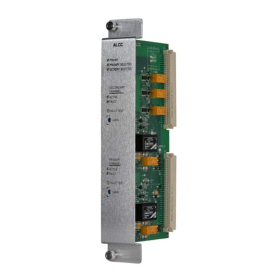
ALCC
POWER
PRIMARY SELECTED
SECNDRY SELECTED
SECONDARY
CHANNEL
ACTIVE
FAULT
FAULT TEST
+
GAIN
_
PRIMARY
CHANNEL
ACTIVE
FAULT
FAULT TEST
+
GAIN
_
Figure 1
ALCC Speaker Line
Output Card
Siemens
Siemens
Industry
Industry
Industry, , , , , Inc.
Siemens
Siemens Industry
Siemens
Industry
Building
Building
Building
Building T T T T T ec
Building
echnologies Di
ec
ec
ec
hnologies Di
hnologies Di
hnologies Di
hnologies Division
Inc.
Inc.
Inc.
Inc.
vision
vision
vision
vision
Advertisement
Table of Contents

Related Manuals for Siemens ALCC


Summary of Contents for Siemens ALCC
-
Page 1: Installation Instructions
FAULT TEST is compatible with AICs located in the remote stations. GAIN The ALCC is transparent to the host system. As such, it supports all styles of wiring supported by ZAC-40 (XLS/ Desigo Fire Safety Modular/Cerberus PRO Modular) as well as ZAC-30 (MXL) amplifiers. It provides supervision... -
Page 2: Operation
AIC input, causing a trouble to be reported to the system. The ALCC relies on the originating amplifier for supervision of the audio risers, and on the AIC for supervision of the connection to the ALCC. Since the AIC monitors the presence of signal on its audio input, it is responsible for reporting audio path faults to the XLS/Desigo Fire Safety Modular/Cerberus PRO Modular system. -
Page 3: Installation
The ALCC plugs perpendicularly into a CC-2 or CC-5 slot via two 96-pin DIN connec- tors and can occupy any slot in the card cage. Slide the ALCC card into the card guides front bezel up, until the card edge connec- tors contact the motherboard receptacles. The LEDs, test buttons, adjustment potentiometers, and the legend should be visible and accessible. - Page 4 Safety Modular/ Modular Cerberus PRO Modular DNET AUDIO AUDIO PRESENT CONTACT REMOTE PAGING STATION EOLR XLSV/Desigo Fire Safety Modular/ Cerberus PRO Modular AUDIO AUDIO PRESENT CONTACT Figure 3 ALCC Example System Wiring Siemens Industry, Inc. P/N 315-050263-3 Building Technologies Division...
- Page 5 Cerberus Cerberus Modular Modular XLSV/Desigo Fire Safety Modular/ Cerberus Modular SECONDARY RISER AUDIO SECONDARY PRESENT CONTACT PRIMARY RISER AUDIO PRIMARY PRESENT CONTACT REMOTE PAGING STATION Figure 4 ALCC Redundant Audio Riser Diagram Siemens Industry, Inc. P/N 315-050263-3 Building Technologies Division...
- Page 6 Figure 5 outlines the input and output connections of the ALCC and the relevant input connections of a nearby AIC. Please refer to AIC Installation Instructions, P/N 315-035300, for details on AIC wiring. In order to ensure correct wiring of the audio riser, please follow the installation instructions for the respective originating amplifiers being used in the global paging stations.
- Page 7 Fire Safety Modular/ Cerberus PRO Modular) ZAC-30 (MXL) CLASS A EOLR 68k OHMS CLASS B EOLR 68k OHMS LAST FIRST ALCC ALCC Figure 6 ALCC Class A and Class B Wiring Diagram Siemens Industry, Inc. P/N 315-050263-3 Building Technologies Division...
-
Page 8: Electrical Ratings
ALCC in the worst case operating condition. These currents are used only for power supply loading calculations. The standby current represents the current consumed from the 24V battery by the ALCC in the quiescent standby mode. This current is used in the battery size calculation.