ADTRAN NetVanta 1230 Series Hardware Installation Manual
Hide thumbs
Also See for NetVanta 1230 Series:
- User manual (4 pages) ,
- Hardware installation manual (28 pages) ,
- Quick start manual (4 pages)

Related Manuals for ADTRAN NetVanta 1230 Series


Summary of Contents for ADTRAN NetVanta 1230 Series
- Page 1 NetVanta 1230 Series Hardware Installation Guide 1700594G1 NetVanta 1234 1700595G1 NetVanta 1234 PoE 1700598G1 NetVanta 1238 1700599G1 NetVanta 1238 PoE 61700594G1-34B July 2009...
- Page 2 To the Holder of the Manual The contents of this manual are current as of the date of publication. ADTRAN reserves the right to change the contents without prior notice. In no event will ADTRAN be liable for any special, incidental, or consequential damages or for commercial losses even if ADTRAN has been advised thereof as a result of issue of this publication.
- Page 3 NetVanta 1230 Series Hardware Installation Guide Conventions Conventions Notes provide additional useful information. Cautions signify information that could prevent service interruption or damage to the equipment. Warnings provide information that could prevent injury or endangerment to human life. 61700594G1-34B Copyright © 2009 ADTRAN, Inc.
- Page 4 Safety Instructions NetVanta 1230 Series Hardware Installation Guide Safety Instructions When using your telephone equipment, please follow these basic safety precautions to reduce the risk of fire, electrical shock, or personal injury: 1. Do not use this product near water, such as a bathtub, wash bowl, kitchen sink, laundry tub, in a wet basement, or near a swimming pool.
- Page 5 Class A prescrites dans la norme sur le materiel brouilleur: “Appareils Numériques,” NMB-003 edictee par le ministre des Communications. Service and Warranty For information on the service and warranty of ADTRAN products, visit the ADTRAN website at http://www.adtran.com/support. 61700594G1-34B...
- Page 6 Service and Warranty NetVanta 1230 Series Hardware Installation Guide Copyright © 2009 ADTRAN, Inc. 61700594G1-34B...
-
Page 7: Table Of Contents
NetVanta 1230 Series ........ - Page 8 Table of Contents NetVanta 1230 Series Hardware Installation Guide Copyright © 2009 ADTRAN, Inc. 61700594G1-34B...
- Page 9 Wallmount Installation ............25 61700594G1-34B Copyright © 2009 ADTRAN, Inc.
- Page 10 List of Figures NetVanta 1230 Series Hardware Installation Guide Copyright © 2009 ADTRAN, Inc. 61700594G1-34B...
- Page 11 Table A-3. 1000Base-T Gigabit Ethernet Port Pinouts ........28 61700594G1-34B Copyright © 2009 ADTRAN, Inc.
- Page 12 List of Tables NetVanta 1230 Series Hardware Installation Guide Copyright © 2009 ADTRAN, Inc. 61700594G1-34B...
-
Page 13: Introduction
PoE. SFP Module Slots The NetVanta 1230 Series devices support two SFP slots that accept a number of industry standard SFP modules. The SFP modules provide Gigabit Ethernet fiber connectivity for high-speed uplinks or switch stacking. The following modules are available for purchase (both of these modules require fiber optic cable with LC connectors): •... - Page 14 After unpacking the unit, inspect it for possible shipping damage. If the equipment has been damaged in transit, immediately file a claim with the carrier and contact ADTRAN Customer Service (refer to the Repair and Replacement section of the Support page on the ADTRAN website at http://www.adtran.com/support).
-
Page 15: Figure 1. Netvanta 1234 Front Panel Layout
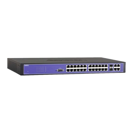
NetVanta 1230 Series Hardware Installation Guide Physical Descriptions NetVanta 1234 Front Panel Design The NetVanta 1234 front panel is shown below. Table 1 on page 20 describes all of the LEDs, and Appendix A on page 27 shows the connector pinouts. -
Page 16: Figure 2. Netvanta 1234 Rear Panel Layout
Physical Descriptions NetVanta 1230 Series Hardware Installation Guide NetVanta 1234 Rear Panel Design The NetVanta 1234 rear panel is shown below. 100-240 VAC 50-60 Hz 0.5A MAX Figure 2. NetVanta 1234 Rear Panel Layout NetVanta 1234 Rear Panel Interfaces Power Connection The rear panel has a power input to the AC universal power supply. -
Page 17: Figure 4. Netvanta 1234 Poe Rear Panel Layout
NetVanta 1230 Series Hardware Installation Guide Physical Descriptions 10/100/1000Base-T Gigabit Ethernet Interfaces The NetVanta 1234 PoE front panel contains four 10/100/1000Base-T Gigabit Ethernet interfaces (RJ-45). These interfaces are arranged in two stacked pairs, with the numbers G1 through G4 screened directly above or below the corresponding port. -
Page 18: Figure 6. Netvanta 1238 Rear Panel Layout
Physical Descriptions NetVanta 1230 Series Hardware Installation Guide 10/100/1000Base-T Gigabit Ethernet Interfaces The NetVanta 1238 front panel contains four Gigabit Ethernet interfaces (RJ-45). These interfaces are labeled G1 through G4 and their status LEDs are located directly over the interfaces. -
Page 19: Figure 8. Netvanta 1238 Poe Rear Panel Layout
NetVanta 1230 Series Hardware Installation Guide Physical Descriptions Mode Selector Button The mode selector button is used to select the type of activity displayed on the LEDs labeled 1 through 48. If LINK/ACT is selected, the LEDs display the link status/activity of the ports. If PoE is selected, the LEDs display the status of PDs connected to the ports. -
Page 20: Table 1. Front Panel Led Descriptions
Physical Descriptions NetVanta 1230 Series Hardware Installation Guide Table 1. Front Panel LED Descriptions Color Indication STAT Power is off. Green (flashing) Power up is in progress. Green (solid) Power is on, power up is complete. LINK/ACT Green (solid) Link status/activity mode selected. -
Page 21: Product Specifications
NetVanta 1230 Series Hardware Installation Guide Product Specifications 3. PRODUCT SPECIFICATIONS Physical Interfaces 10/100Base-T Ethernet interfaces on the front panel 1000Base-T Gigabit Ethernet interfaces on the front panel Combination 1000Base-T Gigabit Ethernet/SFP interfaces on the front panel (SFP slots for fiber connectivity/RJ-45 connectors for copper... -
Page 22: Unit Installation
Unit Installation NetVanta 1230 Series Hardware Installation Guide UNIT INSTALLATION The instructions and guidelines provided in this section cover hardware installation topics, such as mounting options, supplying power to the unit, and installing option cards. These instructions are presented as follows: •... -
Page 23: Mounting Options
NetVanta 1230 Series Hardware Installation Guide Unit Installation Mounting Options The unit may be installed in rackmount or tabletop configurations. The following sections provide step-by-step instructions for rack mounting and tabletop installation. Rack Mounting the NetVanta The NetVanta is a 1U-high, rack-mountable unit that can be installed into a 19-inch equipment rack. The following steps guide you in mounting the NetVanta into a rack. - Page 24 Decide on a location for the NetVanta. The NetVanta 1230 Series is mounted with the front panel facing down as shown in Figure 9 on page 25. Keep in mind that the unit needs to be mounted in a position that allows viewing of the LEDs.
-
Page 25: Supplying Power To The Unit
Figure 9. Wallmount Installation Supplying Power to the Unit The NetVanta 1230 Series units come equipped with an auto-sensing 100 to 240 VAC, 50/60 Hz power supply for connecting to a properly grounded power receptacle. (A detachable power cable with a grounded, three-prong plug comes with the shipment.) To power these units, plug one end of the power cable into the... - Page 26 Unit Installation NetVanta 1230 Series Hardware Installation Guide Your NetVanta is now ready to be configured and connected to the network. For more information on configuration for a specific application, refer to the quick configuration documents provided on the AOS Documentation CD.
-
Page 27: Appendix A. Connector Pin Definitions
Unused Receive Negative 7, 8 — Unused Table A-2. SFP Slot Pinouts Name Name RX_LOS RGND RGND RX_DAT- RGND RX_DAT+ MOD_DEF(0) RGND MOD_DEF(1) VddR MOD_DEF(2) VddT TX_DISABLE TGND TGND TX_DAT+ TGND TX_DAT- TX_FAULT TGND 61700594G1-34B Copyright © 2009 ADTRAN, Inc. -
Page 28: Table A-3. 1000Base-T Gigabit Ethernet Port Pinouts
Appendix A. Connector Pin Definitions NetVanta 1230 Series Hardware Installation Guide Table A-3. 1000Base-T Gigabit Ethernet Port Pinouts Name Description TRD0+ Transmit/Receive Positive TRD0- Transmit/Receive Negative TRD1+ Transmit/Receive Positive TRD2+ Transmit/Receive Positive TRD2- Transmit/Receive Negative TRD1- Transmit/Receive Negative TRD3+ Transmit/Receive Positive... - Page 29 STAT LED 20 NetVanta 1230 brief description 13 tools required for installation 22 NetVanta 1234 front panel 15 rear panel 16 wall mounting instructions 24 NetVanta 1234 PoE warranty 5 front panel 16 rear panel 17 61700594G1-34B Copyright © 2009 ADTRAN, Inc.
- Page 30 Index NetVanta 1230 Series Hardware Installation Guide Copyright © 2009 ADTRAN, Inc. 61700594G1-34B...