Table of Contents
Advertisement
Use & Care Guide
Model No.
153.592500 50 Gallon Tall
153.592600 66 Gallon Tall
153.592800 80 Gallon Tall
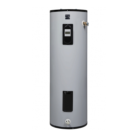
Kenmore
Hybrid Electric Heat Pump
Water Heater
For potable water heating only.
Not suitable for space heating.
INSTALLER: Affix these instructions to or near the water heater.
OWNER: Retain these instructions for future reference.
ADVERTENCIA
Si no puede leer o entender el inglés y necesita el manual de
instrucciones en español, puede solicitarlo al 1-800-821-2017. NO
TRATE DE INSTALAR U OPERAR ESTE CALENTADOR DE AGUA
SI NO ENTIENDE LAS INSTRUCCIONES. No hacer caso de esta
advertencia podría originar lesiones graves o mortales.
P/N 100270593 (0516)
Sears Brands Management Corporation,
Hoffman Estates, IL 60179 U.S.A.
www. kenmore.com
Elite
®
Advertisement
Table of Contents

Related Manuals for Kenmore 153.592500


Summary of Contents for Kenmore 153.592500
- Page 1 Use & Care Guide Model No. 153.592500 50 Gallon Tall 153.592600 66 Gallon Tall 153.592800 80 Gallon Tall Kenmore Elite ® Hybrid Electric Heat Pump Water Heater For potable water heating only. Not suitable for space heating. INSTALLER: Affix these instructions to or near the water heater.
-
Page 2: Table Of Contents
Connec ng the Water Supply ......................15 Verify Connec ons and Fill Tank ......................16 Electrical Connec ons ........................17 Adjus ng the Temperature .........................18 Kenmore® Smart Water Heater Module (sold seperately) ...............20 Diagnos c Codes ..........................24-25 Troubleshoo ng Chart ..........................26 Troubleshoo ng ..........................27-30 Maintenance ............................31-35... -
Page 3: Product Warranty
Master Protection Agreements owner’s manual”” • Power surge protection against electrical damage due to power Congratulations on making a smart purchase. Your new Kenmore fluctuations. Elite® product is designed and manufactured for years of dependable • $300 Food Loss Protection for any food spoilage that is the operation. - Page 4 COMPLETED INSTALLATION TYPICAL TYPICAL INSTALLATION FOR 208V/240V Air Filter Condensate Drain Access Cover Connectivity Port User Interface Module (UIM) Temperature and Shut-off Valve Union* Pressure Relief Valve (Hot) Upper Element and ECO (Outlet) Primary Condensate Drain (3/4” PVC) Discharge Pipe (Do Not Cap or Plug) Thermal Expansion Tank Lower Element...
-
Page 5: Important Safety Informa On
IMPORTANT SAFETY INFORMATION Read and follow all safety messages and instruc ons in Important informa on to keep this manual. Fill out this sec on and keep this manual in the pocket of the water This is the safety alert symbol. It is used to alert you to heater for reference. - Page 6 IMPORTANT SAFETY INFORMATION o reduce the risk of property RISKS DURING OPERATION For informa on about changing the damage, serious injury or death, factory thermostat se ng(s), refer to Scalding Risk read and follow the precau ons below, the “Adjus ng Temperature” sec on in This water heater all labels on the water heater, and this manual (“Step 12”...
- Page 7 IMPORTANT SAFETY INFORMATION According to a na onal standard • Keep the water heater from becom- Maintain the T&P Relief Valve properly. American Society of Sanitary Engineer- ing wet. Immediately shut the water Follow the maintenance instructions ing (ASSE 1070) and most local plumbing heater off and have it inspected by a provided by the manufacturer of the codes, the water heater’s thermostat...
- Page 8 GETTING STARTED • For homes with copper pipes, you Review all of the instruc ons may purchase connector kits with before you begin work. compression fittings that don’t If you aren’t sure that you can require soldering (Figure 1). Com- safely and properly do this work pression fittings are easier to install yourself, contact a qualifi...
-
Page 9: Installa On
INSTALLATION ✓ Follow these steps for proper Water Pressure/ installa on: Thermal Expansion Step 1: Verify that you have a properly sized ✓ Thermal Expansion Tank (Figure 7). We Verify that your recommend installing an expansion home is equipped tank if your home does not have one. and up-to-date for Codes require a properly pressurized, properly sized Thermal Expansion Tank... - Page 10 INSTALLATION BACKGROUND: Water expands when WARNING! Even if the water heater thermostat is set to a rela vely low heated, and the increased volume temperature, hot water can scald. of water must have a place to go, or Install a Thermosta c Mixing Valves at thermal expansion will cause large each point of use to reduce the risk of increases in water pressure (despite...
- Page 11 INSTALLATION The loca on has adequate Water heaters located in The loca on is not prone to space (clearances) for periodic uncondi oned spaces (i.e., physical damage by vehicles, servicing. For op mal water garages, basements etc.) may fl ooding, or other risks. heater effi...
-
Page 12: Removing The Old Water Heater
INSTALLATION Step 3: WARNING! Be sure the water runs When the tank is empty, cool before draining the tank to re- disconnect the Temperature & Removing the old water duce the risk of scalding. Pressure (T&P) Relief Valve discharge pipe. You may be able to heater Connect a garden hose to reuse the discharge pipe, but do not... -
Page 13: Installing The New Water Heater
INSTALLATION Step 4: from all sides and 6 inches from the Measure the distance from top for access to the air filter. the condensate drain access Installing the new • Unit is level to allow proper con- cover to the condensate densate drainage. -
Page 14: Installing Condensate Drain Lines
INSTALLATION • Slope the condensate drain lines WARNING! To avoid serious injury Condensate Drain Access Cover or death from explosion, install a T&P toward the inside fl oor drain or Primary Drain Relief Valve according to the following condensate pump. Connection instruc ons: Secondary Drain... -
Page 15: Shutoff And Mixing Valves
INSTALLATION valves that are compa ble with WARNING! Hot water provided by Terminate the discharge pipe solar hea ng systems can cause severe potable water. Use only full-fl ow ball a maximum of six inches burns instantly resul ng in severe above a fl... - Page 16 INSTALLATION IF YOU HAVE COPPER PIPES: NOTICE: This water heater model con- tains an outlet connec on (J-tube) that If your home has copper water pipes, has an orienta on mark that must line you can solder the water pipe connec- up with arrow (in a 12 o’clock posi on).
-
Page 17: Electrical Connec Ons
INSTALLATION Open a hot water faucet and This water heater requires a A. The length in any ground return path allow the water to run un l it 240/208 VAC single phase 30 does not exceed 6 feet. amp power supply, at 60Hz. B. -
Page 18: Adjus Ng The Temperature
INSTALLATION Operation Step 12: Down buttons on the UIM (User Interface Module). Using the The water heater is now ready for up or down buttons, cycle through Adjus ng the the available temperature set points normal operation. To keep your water Temperature until the desired temperature is dis- heater working safely and efficiently... - Page 19 INSTALLATION Post Installa on Review Water Temperature Ad- simultaneously to help improve recovery. This transi on is seamless justment Understand how to use the and will go unno ced. User Interface Module to set The water temperature can be the various modes and Efficiency Mode - adjusted from 95°F / 35°C to 150°F / func ons.
-
Page 20: Kenmore® Smart Water Heater Module (Sold Seperately)
Connectivity Port and opportunities. Enter button to confirm the number of a seperate control module. See days. When set time for Vacation Mode the Kenmore Smart Water Heater Kenmore® Smart Water has completed, UIM will automatically Module section. Heater Module return to last mode selected. - Page 21 INSTALLATION Temperature Unit Indication Light Temperature Up (Increase) Button °F °C Display Segment DAYS Temperature Down (Decrease) Button Mode/Enter Operational Mode Button Indication Light Vacation Time Indication Figure 26: User Interface Module (UIM) Massachusetts: Install a vacuum relief in cold water line per section 19 MGL 142. Optional Heat Trap Piping Vacuum Relief Valve (when required by local code)
-
Page 22: Diagnos C Codes
DIAGNOSTIC CODES WARNING! Electric Shock Hazard; Disconnect power before servicing. Do not remove the plac c guard from over wiring. Do not touch electrical wiring. Failure to do so can result in death or electrical shock. DISPLAY SHOWS INDICATES CORRECTIVE ACTION - -- --- (series of dashes) Unit is doing a system diagnostic. - Page 23 DIAGNOSTIC CODES WARNING! Electric Shock Hazard; Disconnect power before servicing. Do not remove the plac c guard from over wiring. Do not touch electrical wiring. Failure to do so can result in death or electrical shock. Condensate management 1. Ensure unit is installed level. 2.
- Page 24 TROUBLESHOOTING CHART PROBLEM POSSIBLE CAUSE(S) CORRECTIVE ACTION NO DISPLAY 1. Sleep Mode 1. Touch any button to wake up UIM NO HOT WATER 1. No power to the water heater (No 1. Check for tripped breaker or disconnect. lights on the unit are on). Restore power to unit.
-
Page 25: Troubleshoo Ng
TROUBLESHOOTING WARNING! Working near an energized • Locate the electrical junction box Check the top two screws of the on the side of the water heater and circuit can result in severe injury or death ECO using a non-contact circuit remove the cover. - Page 26 TROUBLESHOOTING Check/Reset Energy Cut Off • Replace the insulation and the upper Debris. In rare cases, debris can s ck in- access panel. ECO Bu on. side the T&P Relief Valve preven ng the valve from sea ng fully. In that case, the •...
- Page 27 TROUBLESHOOTING WARNING! Because higher tempera- A nonfunc oning thermostat or a short- If the hot water is simply not warm tures increase the risk of scalding, if you ed hea ng element can cause extremely enough, there are several possible set the UIM se ng higher than 120°F, hot water.
- Page 28 TROUBLESHOOTING User Interface Module (UIM) set too Lower hea ng element not working. low. If the water temperature at several If the lower hea ng element is not faucets is too cool, adjust the UIM ac- working, you will have some hot water cording to the instruc ons in Step 12 of but not as much as before.
-
Page 29: Maintenance
MAINTENANCE Rou ne Maintenance • Sediment may form large masses that Open the drain valve on the can prevent the tank from draining. water heater. Have a qualified person use a de-lim- Rou ne maintenance will help your ing agent suitable for potable water water heater last longer and work bet- to remove the sediment buildup. - Page 30 MAINTENANCE Anode Rod. The anode rod is a sac- Replacing the Hea ng supply store. rifi cial metal rod that helps reduce Element • Garden hose to drain the tank corrosion and premature failure (leaks) in the tank. The anode rod is a consum- •...
- Page 31 MAINTENANCE Make sure the new element is Once the element is success- Open a hot water faucet and let the hot water run un l it is the correct replacement by fully installed and there are no cool. referring to the water heater’s leaks, replace the power data plate for voltage and wa age wires, thermostat cover, insula on,...
- Page 32 MAINTENANCE • A replacement ECO (available by Mark the wires with tape so T&P Relief Valve Main- calling the number in the repair you’ll know how to put them tenance parts list located on page 34). A back on. business card to check the gap Read and follow the opera ng and between the ECO and tank.
- Page 33 MAINTENANCE • At least every five years, have a NOTE: The water heater may conduct a qualified person inspect the T&P system diagnos c prior to opera on. Relief Valve and discharge pipe. Damage caused by corrosive water Condensate Drain conditions, mineral deposits, or Maintenance other problems can only be deter-...
- Page 34 9005973005 Magnesium* 36” for 50 and 66 gallon Anode (Universal Link Style) 9005742105 42” for 80 gallon Aluminum* Anode Kenmore® Smart Water Heater 58000 Module *Not shown Anode Table 1. 208V/240V 14” for 66 and 80 gallon (50 gallon models have T&P Valve...