Advertisement
Available languages
Available languages
Quick Links
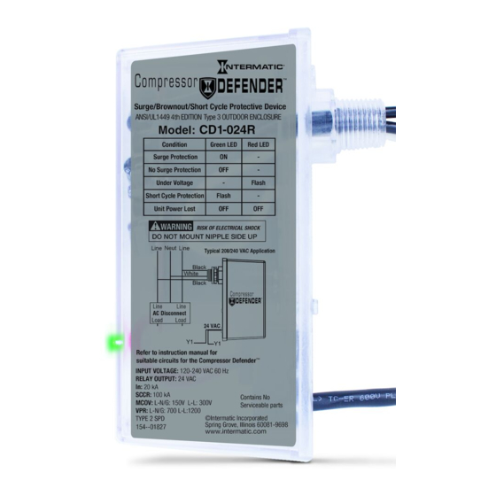
Model CD1-024R Surge/Brownout/Short Cycle Protective Device
IMPORTANT SAFETY INSTRUCTIONS • THOROUGHLY READ AND SAVE THESE INSTRUCTIONS
WARNING
Risk of Fire or Electric Shock
• Disconnect power at the circuit breaker(s) or disconnect switch(es) before installing or servicing.
• Installation and service to be performed by a qualified licensed HVAC technician or licensed electrician.
• More than one circuit breaker or disconnect switch may be required to de-energize the equipment
before servicing.
• Installation and/or wiring must be in accordance with national and local electrical code and/or Canadian
Electrical Code requirements.
• For wet location installations, product should be mounted to a raintight enclosure.
• This device features an internal protection that will disconnect the surge protective
will maintain power to the load--now unprotected. If this is undesirable for the application, follow the
manufacturer's instructions for replacing the device.
• Do NOT mount device nipple side up.
• This product is not designed for rigid conduit mounting.
NOTICE
This unit contains no serviceable parts.
The Compressor Defender™ protects HVAC Compressors (Scroll & Reciprocating), and the electronics
inside central air conditioners, heat pumps, light commercial packaged rooftop units, and mini-splits
from under/overvoltage conditions, surge events, and system short cycling caused from AC power
interruptions.
Specs
• Input voltage: 120/208-240 VAC, 60 Hz
• MCOV (Max Continuous Overvoltage):
L-N/G: 150 V L-L: 300 V
• Type 3 Outdoor Enclosure
• In (Nominal Discharge Rating) : 20 kA
• SCCR (Short Circuit Current Rating): 100 kA
Installing the Compressor Defender™
A typical installation of the Compressor Defender™ connects to the load side of the electrical service
panel and is intended to be installed with over current protection up to 60 amps to the device. The wire
gauge size should be 10 AWG with a minimum wire length of 6 inches to a maximum of 20 inches from
the nipple out.
NOTE: The Compressor Defender™ does not have to be reset after a surge or brownout event.
1. Disconnect condensing unit power at circuit breaker(s), the AC disconnect, and at the 24 VAC
thermostat circuit.
2. Mount the Compressor Defender™ making sure the 24 VAC wire is mounted below the nipple. See
Figure 1.
NOTE: Ensure conductor lengths are as short and straight as possible for best performance. Do
not coil excess wire. The SPD functions best if all bends in wires are rounded, ideally to
a 4 inch radius. Hard 90º bend will reduce efficiency. Cut all leads to the correct length.
NOTE: If you want to install the Compressor Defender™ inside a condensing unit, drill two holes in
the sheet metal and then insert the L clip on the Compressor Defender™ over the holes and
secure the connection with two customer supplied sheet metal screws. See Figure 2.
INSTALLATION INSTRUCTIONS
1
1
• T-stat Normally Closed Relay, 24 VAC
• Output Current Rating: 2 A @ 24 VAC
• VPR (Voltage Protection Rating):
L-N/G: 700 L-L:1200
• Type 2 SPD
• Intended for indoor/outdoor use
• Operating Temp: -40º F to 158º F
(-40º C to 70º C)
component,
but
Advertisement

Summary of Contents for Intermatic CD1-024R
- Page 1 INSTALLATION INSTRUCTIONS Model CD1-024R Surge/Brownout/Short Cycle Protective Device IMPORTANT SAFETY INSTRUCTIONS • THOROUGHLY READ AND SAVE THESE INSTRUCTIONS WARNING Risk of Fire or Electric Shock • Disconnect power at the circuit breaker(s) or disconnect switch(es) before installing or servicing. • Installation and service to be performed by a qualified licensed HVAC technician or licensed electrician.
- Page 2 Gasket Locknut Nipple Black Wire White Wire Disconnect Sheet Black Wire Metal Screw AC Disconnect Box Side Compressor (L/R) Defender™ Housing 24 VAC 24 VAC Thermostat Wire Note: Do not mount the device at the bottom of the disconnect box Figure 2.
- Page 3 Table 1. LED Indicators (Diagnostics) Condition Green LED Red LED Surge Protected − No Surge Protection − Under Voltage − Flash Short Cycle Protect Flash − Unit Power Lost Table 2. Operation See operation table below for an overview of the Compressor Defender™ Operation Condition Description Under Voltage...
- Page 4 (2) What is Not Covered By This Warranty Intermatic does not warrant (a) defects in the Product or damage to any equipment caused by the failure to properly install the Product, (b) damage caused by use of the Product for purposes...
-
Page 5: Instructions D'installation
INSTRUCTIONS D’INSTALLATION Système de protection contre les surtensions/baisses de tension/courts cycles modèle CD1-024R INSTRUCTIONS DE SÉCURITÉ IMPORTANTES • LISEZ ATTENTIVEMENT CES INSTRUCTIONS ET CONSERVEZ-LES AVERTISSEMENT Risque d’incendie ou de choc électrique • Couper l’alimentation aux disjoncteurs ou éteindre les interrupteurs avant toute installation ou toute intervention. - Page 6 Dessus Joint Contre-écrou Mamelon Fil noir Boîtier de Fil blanc sectionneur Fil noir secteur Vis à tôle Boîtier de Côté Boîtier du sectionneur secteur (G/D) Compressor Defender™ 24 V c.a. Fil de thermostat 24 V c.a. Remarque: Ne pas monter l’appareil sur le dessous du boîtier de sectionneur.
- Page 7 Tableau 1. Voyants indicateurs (diagnostic) Situation Voyant vert Voyant rouge Protection contre les surtensions Allumé − Pas de protection antisurtension Éteint − Sous-tension − Clignotant Protection anti-court cycle Clignotant − Perte d’alimentation de l’appareil Éteint Éteint Tableau 2. Fonctionnement Le tableau ci-dessous offre une vue d’ensemble du fonctionnement du Compressor Defender™ Situation Description Sous-tension...
- Page 8 (B) Réparation ou remboursement pour les dommages au matériel correctement raccordé En plus de la garantie décrite ci-dessus, Intermatic offre à l’acheteur initial du Produit, pendant une période de trois ans à compter de la date d’achat, les garanties suivantes : Dans l’éventualité où...
-
Page 9: Instrucciones De Instalación
INSTRUCCIONES DE INSTALACIÓN Dispositivo de protección contra sobretensión, apagado y ciclos cortos modelo CD1-024R INSTRUCCIONES IMPORTANTES DE SEGURIDAD • LEA CUIDADOSAMENTE ESTAS INSTRUCCIONES Y GUÁRDELAS ADVERTENCIA Riesgo de incendio o descarga eléctrica • Se debe desconectar la alimentación eléctrica de los disyuntores o desconectar los interruptores antes de comenzar la instalación o el mantenimiento. - Page 10 Parte superior Junta Contratuerca Boquilla Caja de Cable negro Cable blanco desconexión Cable negro de CA Tornillo Caja de de chapa Carcasa de Lado (I/D) desconexión de CA Compressor Defender™ 24 V CA Cable de termostato de 24 V CA Nota: No monte el dispositivo en la parte inferior de la caja...
- Page 11 Procese una reclamación de seguro de acuerdo con su póliza de seguro de la vivienda. Envíe el Compressor Defender™ a lntermatic para evaluación y prueba al: Coordinador de garantías de Intermatic, 7777 Winn Road, Spring Grove, IL 60081 Cuando recibamos el Compressor Defender™ dañado, lntermatic investigará si el Compressor Defender™...
- Page 12 Cuando Intermatic determine que el Producto está defectuoso, corregirá todo defecto en material o mano de obra mediante el reemplazo del Producto defectuoso. Toda reparación, lo que incluye piezas y mano de obra, será a cargo de Intermatic. La solución anterior es la solución exclusiva del comprador en caso de un incumplimiento de garantía.