Table of Contents
Advertisement
Advertisement
Table of Contents

Subscribe to Our Youtube Channel
Related Manuals for Gossen MetraWatt GEOHM C


Summary of Contents for Gossen MetraWatt GEOHM C
- Page 1 Operating Instructions ® GEOHM C-GB int. 3-349-089-03 Earth Tester 16/5.18...
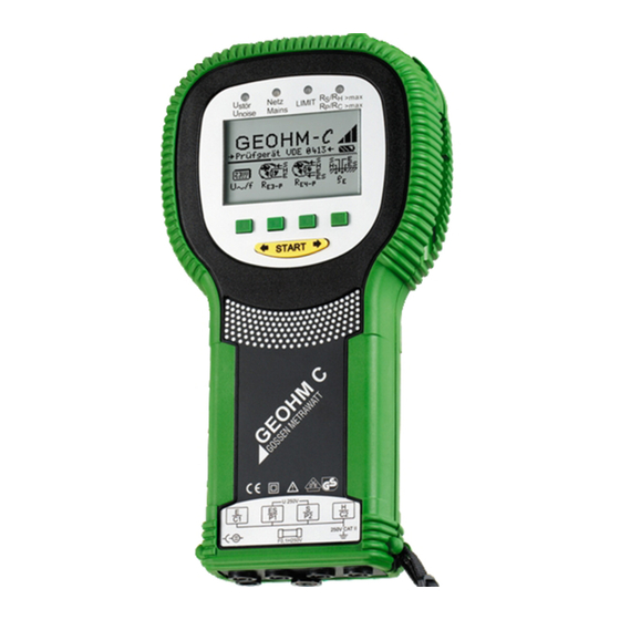
- Page 2 ® ® GEOHM C Measuring and Test Instrument GEOHM C Control and Display Unit Interface Adapter Infrared Interface (for plug-on instructions see page 3) Control and Display Unit Signal Lamps >max Netz stör LIMIT Mains >max noise Battery Level Display The scroll bar indicates which menu is currently active.
- Page 3 ® PC software WinProfi for communication with GEOHM The free PC starter software WinProfi is used for communication with ® your GEOHM C test instrument. WinProfi is available on our homepage with the following content and functions: • up-to-date test instrument software –...
-
Page 4: Table Of Contents
Contents Contents Page Page Applications ..................5 Database Function ................25 Creating a Data Record – Data Function ............25 Safety Features and Precautions ............6 Saving Measured Values to Memory – STORE Function ........26 Terminology ..................7 Querying Data Records – View Function ............27 6.3.1 Deleting a Data Record from within a Memory Address –... -
Page 5: Applications
Applications This instrument fulfills the requirements of the applicable EU guidelines Correct Positioning of the Earth Electrode and national regulations. We confirm this with the CE marking. The rele- Earth electrodes and earthing systems must always demonstrate the lowest possible overall resistance relative to the ground reference plane vant declaration of conformity can be obtained from GMC-I Messtechnik GmbH. -
Page 6: Safety Features And Precautions
The voltage drop which occurs due to earthing resistance R , and which • After excessive stress due to transport is measured at terminals ES or E and S, is first fed first to an electronic filter • After lengthy periods of storage under unfavorable conditions which is synchronous to the generator, and then to a synchronously ... -
Page 7: Terminology
Terminology In order to assure that the terminology used in these operating instruc- tions is not misunderstood, the most important terms are defined below. Earth: a term used as a designation for the planet Earth, as well as a connection to ground. -
Page 8: Initial Start-Up
Initial Start-Up Rechargeable NiCd or NiMH batteries may be used as well. Be absolutely sure to refer to chapter 8.2 on page 31 regarding the charging cycle and Switching the Instrument On and Off the charging adapter. Always replace the batteries in complete sets. Dispose of batteries in an environmentally sound fashion. -
Page 9: Selecting Menus And Configuring Basic Settings
Selecting Menus and Configuring Basic Settings Setting the Clock START Ð Activate the Time key. The cursor appears at the first digit in the date. Enter the desired Ð numeral with one of the softkeys. Numerals which do not appear can be displayed with the help of the or the key. - Page 10 Default Settings – Last Used Settings Setting On-Time, Manual Shutdown A selection can be made here as to whether the menus will be displayed according to the default settings, or if the last opened menus should be displayed. Ð Press the Setup key. Ð...
- Page 11 Background Illumination and Contrast Self-Test LCD Illumination Contrast high Ð Ð Press the Display key. The self-test is started from the main menu with the Test key. The test has a duration of several minutes. Ð In order to extend battery service life, display illumination can be switched off entirely.
-
Page 12: Downloading A Software Update, Managing Report Data
Ð Display: Press the Test key after each test pattern has been displayed A Install WinProfi to the PC and Start the Program Download the WinProfi software from our international homepage: in order test the display elements. Ð www.gossenmetrawatt.com Ð... - Page 13 B Prerequisites for Software Update or Data Exchange C Transmission of a Software Update to the Test Instrument ® Ð Find the interface to which the GEOHM C is connected. Ð PC: Select the Update All function from the Update menu. Follow the in- structions which appear at the monitor.
- Page 14 D Managing Report Data • Edit or transmit report templates ® Ð Connect the GEOHM C test instrument with your PC via the interface adapter IrDa-USB converter Ð Start WinProfi. Ð Switch on the test instrument. ® Ð Set the on-time period of the GEOHM C to „>>>>>“, to give you enough time for adjusting the settings in WinProfi before the test in- strument switches off again automatically, see chapter 4.5.
-
Page 15: Operation
Operation LED Functions LED lights Measuring Func- Significance Remedy Display Functions up red tion The following items are displayed at the LCD: Interference Interference voltage in the soil Wait until the interference voltage Stör noise voltage to be measured exceeds the clears on its own, or insert the test •... -
Page 16: Voltage Measurement
Voltage Measurement Earth Resistance Measurements in General Perform measurements as follows after setting up the measuring circuit as described in the following sections: Ð In order to select the desired measurement type, press the R E3-P key for 3-pole, or the R key for 4-pole earth resistance measure- E4-P ment in accordance with the measuring circuit setup. -
Page 17: Configuring The Measuring Range - Range Function
5.4.1 Configuring the Measuring Range – RANGE Function Manual Measuring Range Selection Automatic Measuring Range Selection As a rule, you will not need to use manual measuring range selection unless no measurement value is displayed, or if greatly fluctuating If automatic measuring range selection is used, the instrument selects the highest possible current it is capable of transmitting from the earth ... -
Page 18: Setting A Limit Value - Limit Function
5.4.2 Setting a Limit Value – LIMIT Function Measuring Earthing Resistance If required, an earthing resistance limit value R can be selected by press- 5.5.1 Measuring Circuit Setup, Measuring Instructions ing the LIMIT key. If measured values in excess of this limit value occur, the red LIMIT LED lights up. - Page 19 Note Note Measurement cables must be well insulated in order to avoid Measurement cables must be well insulated in order to avoid shunting. In order to reduce coupling influence to a minimum, shunting. In order to reduce coupling influence to a minimum, measurement cables should neither cross one another, nor should measurement cables should neither cross one another, nor should they run parallel to each other over long distances.
- Page 20 If the same measured value results from all 3 measurements, the correct In such cases, correct measure- earthing resistance value has been obtained and the probe is in the ment results can be obtained ground reference plane. either by increasing the distance between the earth electrode and However, if these 3 measured values differ from one another, either the the auxiliary earth electrode, or by...
- Page 21 Ð Measured resistance values are subsequently displayed as a table, and then as a graphic representation (curve I in Figure 6 on page 21). Curve I (CI) Curve II (CII) If a parallel line is drawn through inflection point S1 to the abscissa, the ...
-
Page 22: Measuring Soil Resistivity
Measuring Soil Resistivity The dissemination resistance value of a given earth electrode is depen- dent upon soil resistivity. Soil resistivity must be known in order to allow for advance calculation of dissemination resistance for the design of earthing systems. Soil resistivity (see also chapter 3 on page 7) can be measured with the ®... -
Page 23: Calculating Dissemination Resistance
5.6.2 Calculating Dissemination Resistance The following table includes formulas for calculating dissemination + resistance for various types of earth electrodes. These rule-of-thumb formulas are entirely adequate for practical application. Number Earth Electrode Type Formula Auxiliary Information 2 ... -
Page 24: Measuring Ohmic Resistance
Measuring Ohmic Resistance Note The resistance of liquid and solid conductors can be measured with the ® Cable resistance can be measured with this test setup. GEOHM C earth tester, as long as they are capacitance and induction- free. 5.7.2 4-Wire Connection 5.7.1 2-Wire Connection Ð... -
Page 25: Database Function
Database Function Displayed measurement data can be saved individually for each measure- M-TYPE Setting Significance ment to the internal database either with or without a comment. In order Continuity to metallic installations to assign the individual measured values to various buildings, customers Continuity to metallic gas lines etc., a data record must first be created with its own memory address. -
Page 26: Saving Measured Values To Memory - Store Function
Ð Entries can be made to the BUILDING, M-TYPE and CUSTOMER ID fields Saving Measured Values to Memory – STORE Function Ð one after the other, and a building designation can be entered with the Start the desired measurement. The STORE softkey is displayed after help of the softkeys. -
Page 27: Querying Data Records - View Function
Querying Data Records – View Function 6.3.1 Deleting a Data Record from within a Memory Address – View Function Press the Del key. No security requests appear. Ð Ð Press the View key. Data record numbering is changed as soon as an individual data re- Ð... -
Page 28: Delete All Memory Addresses - Data Function
6.3.3 Delete All Memory Addresses – Data Function Ð Up to 250 data records can be stored to memory. The memory is full Acknowledge by simultaneously pressing O and K to delete all data when the triangle to the right of the “MEMORY:” parameter is entirely filled in. from memory. -
Page 29: Characteristic Values
Characteristic Values Meas. Impedance, Intrinsic Measuring Display range Measuring Range Qty. Test Current Uncertainty Uncertainty 0.01 ... 20 1.0 ... 20 (10 % rdg. + 6d) 10 mA 0.1 ... 200 5 ... 200 (10 % rdg. + 6d) 1 mA 1 ... - Page 30 Electrical Safety Display Values including Allowances for Measuring Error Safety Class I I per IEC 61 010-1 Table for the determination of maximum display values for low earth resis- tances by making allowances for the tester’s measuring error: Operating Voltage 250 V Test Voltage 2.3 kV...
-
Page 31: Maintenance
Maintenance Battery Operation When only one solid segment remains in the battery symbol, the batteries Housing must be replaced, or recharged if rechargeable batteries are used. No special maintenance is required for the housing. Keep outside surfaces clean. Use a slightly dampened cloth and/or a special purifier for synthetic material for cleaning. -
Page 32: Fuses
Ð 5 segments of the battery symbol are continuously displayed in a sweep- Remove the threaded fuse cap with the help of a suitable tool (e.g. a ing pattern from left to right for the entire duration of the charging cycle. screwdriver) by pressing and turning counterclockwise. -
Page 33: Repair And Replacement Parts Service
We are pleased to perform DAkkS or factory calibrations for you in our Competent Partner calibration laboratory. Please visit our website at GMC-I Messtechnik GmbH is certified in accordance with www.gossenmetrawatt.com ( Company Quality and Certificates DIN EN ISO 9001. - Page 34 GMC-I Messtechnik GmbH...
- Page 35 GMC-I Messtechnik GmbH...
- Page 36 Edited in Germany Subject to change without notice A pdf version is available on the internet. Phone +49 911 8602-111 GMC-I Messtechnik GmbH +49 911 8602-777 Südwestpark 15 e-mail info@gossenmetrawatt.com 90449 Nürnberg • Germany www.gossenmetrawatt.com...
Need help?
Do you have a question about the GEOHM C and is the answer not in the manual?
Questions and answers