
Related Manuals for Samson 3310/AT


Summary of Contents for Samson 3310/AT
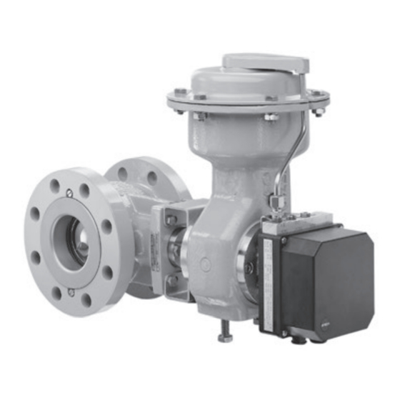
- Page 1 EB 8222 EN Translation of original instructions Type 3310/3278 with positioner Type 3310/AT Type 3310/AT and Type 3310/3278 Pneumatic Control Valve Type 3310 Segmented Ball Valve Edition December 2016...
- Page 2 Î For the safe and proper use of these instructions, read them carefully and keep them for later reference. Î If you have any questions about these instructions, contact SAMSON‘s After-sales Service Department (aftersalesservice@samson.de). The mounting and operating instructions for the devices are included in the scope of delivery.
-
Page 3: Table Of Contents
Contents General safety instructions ................5 Design and principle of operation ..............6 Fail-safe position ....................6 2.1.1 Type SRP (single-acting version) ..............6 2.1.2 Type DAP (double-acting version) ..............8 Mounting ......................8 Assembling valve and actuator ...............8 3.1.1 Type 3310-SRP ....................8 3.1.2 Type 3310/3278 ...................9 Mounting position ..................11 Signal pressure connection ................11 Operation ....................12 Changing the fail-safe action ................12... - Page 4 EB 8222 EN...
-
Page 5: General Safety Instructions
The declaration of conformity can be viewed and downloaded at u http://www.samson.de. − To ensure appropriate use, only use the valve in applications where the oper- ating pressure and temperatures do not exceed the specifications used for siz- ing the valve at the ordering stage. -
Page 6: Design And Principle Of Operation
(1). The actuator motion is trans- Type 3310 Segmented Ball Valve and either mitted to the segmented ball valve by a shaft the SAMSON PFEIFFER Type AT or the with square or key drive. The valve shaft (4) SAMSON Type 3278 Pneumatic Rotary is sealed by a self-adjusting PTFE V-ring Actuator. - Page 7 Design and principle of operation SAMSON Type 3278 Actuator SAMSON PFEIFFER Type AT Actuator 12.1 12.2 13.2 13.1 11.3 11.4 11.5 11.6 11.7 Note 11.8 Detail A (seal) is shown in Fig. 3. 11.1 11.2 10 10.1 10.3 10.2 Fig. 1: Sectional drawing of Type 3310 Valve...
-
Page 8: Type Dap (Double-Acting Version)
When the pressure is relieved from the Proceed as follows if the valve and actuator rotary actuator or the supply air fails, the have not been assembled by SAMSON: actuator springs open the valve. The valve closes opposing the force of the actuator Note springs when the signal pressure increases. -
Page 9: Type 3310/3278
If the valve and actuator have not been as- ed ball stops at an opening angle of 90°. sembled by SAMSON, mount the actuator 8. Lock the position of the stop bolt with the onto the body flange 1 or 2 depending on lock nut. - Page 10 Mounting The four feather key notches on the actuator 9. Lock the position of both stop bolts with shaft arranged every 90° allow the rotary the lock nuts. actuator to be mounted on the segmented Fail-open ball valve offset at angles of 90° in such a 1.
-
Page 11: Mounting Position
− The standard direction of flow (onto the segmented ball) is indicated by SAMSON by an arrow on the valve body. − If the direction of flow is be reversed, e.g. required for abrasive media, indi-... -
Page 12: Operation
Operation 4 Operation Î If you intend to remove parts to clean them, first mark the position of the seat ring (11.8) in the body for a valve with 4.1 Changing the fail-safe soft-seated ball. This will help you to re- action place the seat ring in its correct position on reassembling the valve. -
Page 13: Replacing The Seat Ring Seal
Servicing 2. Pull all the packing parts out of the pack- 3. Soft-seated version: remove the support ing chamber using a suitable tool. Clean ring (11.7) and seat ring (11.8). the packing chamber thoroughly. Metal-seated version: remove in 3. Renew the packing (2.3). Slide the pack- sequence any washer(s) (11.4), metal ing parts over the shaft (4) into the pack- tubular seal (11.5) and seat ring (11.6). - Page 14 Servicing 11.7 11.5 11.8 11.6 11.4 Soft-seated version Metal-seated version Seal 11.1 11.2 11.3 Body Soft-seated version: Metal-seated version: Segmented ball 11.7 Support ring 11.4 Washer Retainer 11.8 Seat ring (PTFE) 11.5 Metal tubular seal 11.1 Screw 11.6 Seat ring (metal) 11.2 Washer Fig. 3: Seat ring seal...
-
Page 15: Replacing The Segmented Ball, Shafts And Bearings
Servicing 5.5 Replacing the segmented 6. Use snap ring pliers to pull the snap ring (4.3) off the shaft and pull the shaft out ball, shafts and bearings of the body using disassembling tool. 7. Pull all the packing parts out of the pack- NOTICE ing chamber using a suitable tool. - Page 16 Servicing assembling tool to press the bearing 5.4) on the bearing bushing (5.1) and bushing into the segmented ball. use the packing gland (2) to press them 3. Use the part of the tool that is in the bearing of the support shaft to slide the 5.
-
Page 17: Changing The Characteristic
Changing the characteristic 7. Mount the packing with spacer (2.7), washer (1.6), spring (2.5), thrust washer (2.4), packing (2.3) and packing gland (2). Checking the friction torque Check the friction torque (breakaway torque) needed to open the valve according to Ta- ble 4. -
Page 18: Tools And Tightening Torques
Tools and tightening torques 7 Tools and tightening torques 7.1 Special tools Table 3: Special tools Tool to mount and remove the Extracting tool for retainer (11) Extracting tool shaft for support Press tool for Press tool for shaft (5) Crossbeam Flange support shaft actuator shaft... -
Page 19: Tightening Torques
Tools and tightening torques 7.2 Tightening torques Table 4: Tightening and friction torques Valve size 1½ Tightening torques in Nm Screws (2.2) on packing gland Bolts (10.3) on bottom flange Friction torque to open the valve in Nm Metal seal Soft seal 7.2.1 Tightening torques for flange bolts Table 5: ANSI version... - Page 20 Tools and tightening torques Table 6: DIN version Flange bolts Min. tightening torque (quality 8.8) in Nm 10/40 4 x M12 10/40 4 x M16 10/40 4 x M16 10/16 8 x M16 25/40 8 x M16 10/16 8 x M16 25/40 8 x M20 10/16 8 x M20...
-
Page 21: Nameplate
Nameplate 8 Nameplate The nameplate includes all details required to identify the valve. SAMSON 3310 - 90˚ 70˚ Made in france Fig. 5: Nameplate Type number Serial number Valve size DN .../NPS ... Plug seal: Metal seal PTFE PEEK 450G Victrex ® PK1 PEEK 450FC30 Victrex ®... -
Page 22: Accessories
Accessories 9 Accessories Table 7: Accessories Connecting Actuator area Type SRP/DAP Mounting kit Mounting kit flange in cm² Actuator (AT) order no. order no. DIN 3337 (Type 3278) 1400-7316 1400-7251 1400-7316 1½ 1400-7317 1400-7348 160 (F07) 1400-7239 1400-7239 1400-7252 1400-7239 1400-7239 1400-7732 1400-7240 1400-7240 1400-7241 320 (F12) 1400-7255... -
Page 23: Technical Data
Technical data 10 Technical data 11 Customer inquiries The technical data as well as the dimensions Please submit the following details: and weights for the DIN and ANSI versions − Order number (specifications on the of the Type 3310 Segmented Ball Valve are nameplate) listed in the corresponding Data Sheet −... - Page 24 EB 8222 EN SAMSON AKTIENGESELLSCHAFT Weismüllerstraße 3 · 60314 Frankfurt am Main, Germany Phone: +49 69 4009-0 · Fax: +49 69 4009-1507 samson@samson.de · www.samson.de...