
Related Manuals for Wolf MW24-1100


Summary of Contents for Wolf MW24-1100
- Page 1 800.222.7820 MW24-1100 Standard Microwave Service Manual General Information Installation Information Controls & Operation Component Access & Removal Troubleshooting Guide Wiring Diagrams...
- Page 2 Wolf appliance units by anyone other than Authorized Service Technicians. The information and images contained in this manual are the copyright property of Wolf appliance, Inc. Neither this manual nor any information or images contained herein may be copied or used in whole or in part without the express written consent of Wolf Appliance, Inc.©, all rights reserved.
-
Page 3: General Information
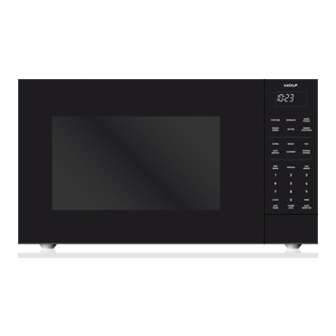
MW24-1100 MICROWAVE OVEN WARRANTY INFORMATION This page contains a summary of the 2 & 5 Year Warranty that is supplied with every Wolf product, followed by a Non Residential Warranty summary and then notes about the warranties. TWO & FIVE YEAR Warranty Summary •... - Page 4 General Information MW24-1100 MICROWAVE OVEN MODEL FEATURES Listed below are some features of the Wolf microwave. (See Figure 1-3) 1. One Touch Door Open Button 2. Safety Door Latches (Two) NOTE: The oven will not operate unless the door is securely closed.
-
Page 5: Installation Information
Installation Information MW24-1100 MICROWAVE OVEN Built-In Wall Installation The Wolf 24” microwave can be set into a built-in wall installation with the use of a 30” trim kit, available from a Wolf dealer or distributor. Decorative The trim kit consists of a ductwork assembly, duct... - Page 6 Installation Information MW24-1100 MICROWAVE OVEN INSTALLATION INFORMATION The Wolf microwave oven can be set up as a free- TO AVOID SHOCK HAZARD, NEVER REMOVE THE standing unit or set into a built-in wall installation. GROUND PRONG FROM THE PLUG OF THE POWER SUPPLY CORD.
- Page 7 Theory of Operation MW24-1100 MICROWAVE OVEN DESCRIPTION AND FUNCTION OF Switches and Relays Interaction: COMPONENTS 1. When the door is opened, the monitor switch con- tacts close (to the ON condition) due to their being normally closed. At this time the primary interlock...
- Page 8 Theory of Operation MW24-1100 MICROWAVE OVEN Power Transformer Magnetron The power transformer converts 115 volts AC to approx- The magnetron converts the high voltage from the volt- imately 3.3 volts AC on the filament winding which age doubler circuit to microwave energy, then feeds the heats the magnetron filament.
- Page 9 Theory of Operation MW24-1100 MICROWAVE OVEN Touch Control Panel Assembly 4. Relay Circuit The touch control section consists of the following units: A circuit to drive the magnetron, fan motor, turntable motor and light the oven lamp. 1. Key Unit 2.
- Page 10 (approximately 1”), causing the food’s water and fat molecules to vibrate very rapidly which generates heat within the food to cook it in a very short time. A Wolf microwave oven uses mechanical components and elec- trical circuits in various combinations to produce and control the output of microwave energy. The electromechanical system of the microwave oven consists of two fundamental sections, the Control Section and the High-Voltage Section.
- Page 11 Theory of Operation MW24-1100 MICROWAVE OVEN The High Voltage Section The high voltage section consists of the power transformer, doubler circuit and the magnetron. If the control section is operating properly and supplying 115V AC to the power transformer, the transformer will con- vert the 115V AC to approximately 2300V AC.
- Page 12 MW24-1100 MICROWAVE OVEN DETAILED OPERATING SEQUENCE The Simple Theory of Operation on the previous pages explains the basics of how a Wolf microwave oven works. This Detailed Operating Sequence explains the component functions in greater detail during oven operation. Off Condition Closing the door activates the door sensing switch and secondary interlock switch.
- Page 13 Theory of Operation MW24-1100 MICROWAVE OVEN 3. The filament winding voltage heats the magnetron filament and the voltage from the high voltage winding is sent to a voltage doubler circuit. 4. The microwave energy produced by the magnetron is channeled through the waveguide into the cavity feed-box, and then into the cavity where the food is placed to be cooked.
- Page 14 Theory of Operation MW24-1100 MICROWAVE OVEN Power Level Cooking, P-0 (0%) to P-HI (100%) When Variable Cooking Power is programmed, the 115 volts AC is supplied to the power transformer intermit- tently through the contacts of relay (RY-2) which is operated by the control unit within a 32 second time base.
- Page 15 Theory of Operation MW24-1100 MICROWAVE OVEN ABSOLUTE HUMIDITY SENSOR CIRCUIT Detector Circuit of AH Sensor Circuit The detector circuit detects the output voltage of the absolute humidity circuit, which allows the LSI Structure of AH Sensor to control sensor cooking. When the unit is set to...
- Page 16 Theory of Operation MW24-1100 MICROWAVE OVEN MODES OF OPERATION AND FEATURES This portion of the manual explains the input key strokes performed at the touch control panel in order to begin, use and end different modes of operation and to enable specific features of the microwave oven. For more detailed information on any of the following articles, refer to the complete Microwave Oven Use and Care Guide, supplied with the unit.
- Page 17 Theory of Operation MW24-1100 MICROWAVE OVEN Clock ON/OFF Feature After the time of day is set, it may be desired to switch the clock display off. To do this, follow the steps below: 1. Press the HELP key and five help features will flash on the display, the fifth one will read “CLOCK DISPLAY - ON OR OFF - PRESS 5 ”...
- Page 18 Theory of Operation MW24-1100 MICROWAVE OVEN Manual Time Cook Mode The microwave oven can be programmed for up to 99 minutes and 99 seconds of cooking time, at various power levels. (To explain basic Manual Time Cook Mode, the power level will not be adjusted in this example.) To initiate Time Cook Mode, follow the steps below:...
- Page 19 Theory of Operation MW24-1100 MICROWAVE OVEN Power Level Table Touch POWER LEVEL Key Number of Times Indicated for Desired Power Level Percent of Microwave Power Common Term for Power Levels POWER LEVEL Key X 1 100% High POWER LEVEL Key X 2...
- Page 20 Theory of Operation MW24-1100 MICROWAVE OVEN Quick ON Mode If the microwave oven is off and the QUICK ON/START key is pushed and held, the microwave oven will auto- matically switch on at 100% power and the display will flash a one-second count, starting with “1 “...
- Page 21 Theory of Operation MW24-1100 MICROWAVE OVEN Keep Warm Mode Keep Warm Mode allows food to be kept warm up to 30 minutes. To initiate Keep Warm Mode, follow the steps below: 1. Press the KEEP WARM key and “ENTER TIME ”...
- Page 22 Theory of Operation MW24-1100 MICROWAVE OVEN Multiple Sequence Feature The Multiple Sequence Feature allows up to four dif- ferent time and power level adjustments to occur in a programmed sequence. For example, it’s possible to defrost, cook and keep food warm without having to reprogram the microwave for each feature.
- Page 23 Theory of Operation MW24-1100 MICROWAVE OVEN Auto Start Feature The Auto Start Feature allows the microwave oven to begin cooking automatically at a designated time of day (within 12 hours from program input). To program the Auto Start Feature, follow the steps below: 1.
- Page 24 Theory of Operation MW24-1100 MICROWAVE OVEN Auto Defrost Mode Auto Defrost Mode is to be used while referencing the Super Defrost and Auto Defrost charts in the Use and Care Guide, supplied with the microwave oven. NOTE: If defrosting foods not found on the Super Defrost or Auto...
- Page 25 Theory of Operation MW24-1100 MICROWAVE OVEN Auto Sensor Cooking Modes Auto Sensor Cooking Modes are to be used while refer- encing the recipes and related charts in the Use and Care Guide, supplied with the microwave oven. When the microwave is in a Sensor Cooking Mode, food is cooked without figuring time, power level or quantity.
- Page 26 Theory of Operation MW24-1100 MICROWAVE OVEN Auto Meal /Beverage / Recipe Cook Modes The key strokes described here cover the following keys on the control panel: BREAKFAST, LUNCH, DINNER, BEVERAGE and RECIPE. The Auto Meal / Beverage / Recipe Cook Modes are to be...
- Page 27 Theory of Operation MW24-1100 MICROWAVE OVEN Help Features There are five help features accessible by pressing the HELP key. When the HELP key is pressed they will flash on the digital display in this order: • CHILD LOCK - PRESS ONE •...
- Page 28 Theory of Operation MW24-1100 MICROWAVE OVEN Demonstration Mode Demo Mode was incorporated into the software of the microwave oven to so that the appliance could be used in a showroom setting, allowing the keys to be pressed and the display to function, without allowing power to the microwave cooking components.
- Page 29 Component Removal MW24-1100 MICROWAVE OVEN COMPONENT ACCESS AND REMOVAL This section explains how to adjust, access and remove components in a model MW24 Microwave Oven. An attempt has been made to arrange these procedures in such a way as to simulate which components would need to be removed first in order to gain access to other components.
- Page 30 Component Removal MW24-1100 MICROWAVE OVEN Turntable Tray and Turntable Support Tray The collar at the bottom center of the turntable support is placed onto the shaft of the turntable motor. The turntable tray sits on top of the turntable support.
- Page 31 Component Removal MW24-1100 MICROWAVE OVEN Door Assembly (with Door Panel and Latch Head) The door hinge pins, which are part of the door frame, Door Assy. fit down into holes in the oven hinges. To remove the door assembly, the choke cover will first need to be removed.
- Page 32 Component Removal MW24-1100 MICROWAVE OVEN Power Supply Cord Power Supply Cord The power supply cord is attached to the back of the microwave oven with a screw. To remove the power supply cord, the cabinet case must first be removed. Then, unplug the electrical leads from the terminals.
- Page 33 Component Removal MW24-1100 MICROWAVE OVEN Latch Hook/Switch Assembly Push lever Pull connector Terminal The latch hook/switch assembly consists of the latch hook, door sensing switch, secondary interlock switch, monitor switch, monitor switch fuse and fuse holder. Plastic tabs on the latch hook fit into slots in the oven cavity frame.
- Page 34 Component Removal MW24-1100 MICROWAVE OVEN C/T Fuse Push lever Pull connector Terminal The C/T fuse is held to the chassis support with a screw. To remove the C/T fuse, the cabinet case must first be removed. Then, use a needle-nose pliers to disconnect the “Positive-Lock”...
- Page 35 Component Removal MW24-1100 MICROWAVE OVEN Cooling Fan Duct, Fan Blade and Fan Motor Two screws mount the cooling fan to the back cover of Duct the oven cavity. The fan blade is inserted onto the fan shaft and a small amount of Loc-tite is applied to help hold the blade on the shaft.
- Page 36 Component Removal MW24-1100 MICROWAVE OVEN Capacitor, Capacitor Band and Rectifier Push lever Pull connector Terminal The capacitor is held in place by the capacitor band. The capacitor band is attached to the base plate with a screw on one side, while the other side fits into a chan- nel in the base plate.
- Page 37 Component Removal MW24-1100 MICROWAVE OVEN Push lever Cavity Temperature Fuse Pull connector Terminal The cavity temperature fuse is attached to the top left side of the oven cavity with a screw. To remove the cavity temperature fuse, the cabinet case must first be removed. Then, use a needle-nose Positive pliers to disconnect the “Positive-Lock”...
- Page 38 Component Removal MW24-1100 MICROWAVE OVEN Turntable Motor, Cushion, Motor Packing and Motor Snip material Cover between knock-out holes. NOTE: 13-1/4 lbs. (6 kg.) is maximum weight limit for turntable motor. The turntable motor is attached to the bottom side of the oven cavity with a screw.
- Page 39 Troubleshooting & Tech Data MW24-1100 MICROWAVE OVEN TROUBLESHOOTING AND TECHNICAL DATA This section of the manual combines the Troubleshooting Guide with Technical Data. The troubleshooting table on the following page lists the condition and problems, as well as which parts need to be replaced or checked and which test procedures to follow.
- Page 40 Troubleshooting & Tech Data MW24-1100 MICROWAVE OVEN How to use this table: CK = Check Parts Listed RE = Replace Parts Listed (after verifying defects) All other letters indicate which test procedure to be performed. Test procedures can be found in alphabetical order on the following pages.
-
Page 41: Test Procedures
Troubleshooting & Tech Data MW24-1100 MICROWAVE OVEN TEST PROCEDURES PROCEDURE COMPONENT TEST LETTER MAGNETRON ASSEMBLY TEST Disconnect power supply cord and remove outer cabinet case. Open door and block it open. Discharge high-voltage capacitor. To test for an open filament, isolate the magnetron from the high voltage circuit. A continuity check across the magnetron filament leads should indicate less than 1 ohm. - Page 42 Troubleshooting & Tech Data MW24-1100 MICROWAVE OVEN TEST PROCEDURES PROCEDURE COMPONENT TEST LETTER HIGH-VOLTAGE RECTIFIER TEST Disconnect power supply cord and remove outer cabinet case. Open door and block it open. Discharge high-voltage capacitor. Isolate the rectifier from the circuit. Using the highest ohm scale of the meter, read the resistance across the terminals and observe meter reading, then reverse the leads to the rectifier terminals and observe meter reading.
- Page 43 Troubleshooting & Tech Data MW24-1100 MICROWAVE OVEN TEST PROCEDURES PROCEDURE COMPONENT TEST LETTER (CONTINUED) (CONTINUED) Reconnect all leads removed from components during testing. Reinstall the outer cabinet case, then reconnect power supply cord. Run the oven and check all functions.
- Page 44 Troubleshooting & Tech Data MW24-1100 MICROWAVE OVEN TEST PROCEDURES PROCEDURE COMPONENT TEST LETTER BLOWN C/T FUSE TEST Disconnect power supply cord and remove outer cabinet case. Open door and block it open. Discharge high-voltage capacitor. If the monitor fuse is blown when the door is opened, check primary interlock relay as described earlier. If primary interlock relay indicates proper operation, replace the the complete Latch Hook/Switch Assembly.
- Page 45 Troubleshooting & Tech Data MW24-1100 MICROWAVE OVEN TEST PROCEDURES PROCEDURE COMPONENT TEST LETTER (CONTINUED) (CONTINUED) The corresponding segments of all digits do not light up; or they continue to light up. Wrong figure appears. A certain group of indicators do not light up.
- Page 46 Troubleshooting & Tech Data MW24-1100 MICROWAVE OVEN TEST PROCEDURES PROCEDURE COMPONENT TEST LETTER RELAY TEST Disconnect power supply cord and remove outer cabinet case. Open door and block it open. Discharge high-voltage capacitor. Disconnect the leads to the primary of the power transformer and ensure that these leads remain isolated from other components and oven chassis by using insulation tape.
- Page 47 Troubleshooting & Tech Data MW24-1100 MICROWAVE OVEN TEST PROCEDURES PROCEDURE COMPONENT TEST LETTER FOIL PATTERN ON THE PRINTED WIRING BOARD TEST NOTE: To protect the electronic circuits, this model is provided with a fine foil pattern added to the primary on the PWB, this foil pattern acts as a fuse.
- Page 48 Troubleshooting & Tech Data MW24-1100 MICROWAVE OVEN TEST PROCEDURES PROCEDURE COMPONENT TEST LETTER AH SENSOR TEST (Checking the initial sensor cooking condition) WARNING: THE OVEN SHOULD BE FULLY ASSEMBLED BEFORE PERFORMING THE FOLLOWING PRO- CEDURE. The oven should be plugged in at least two minutes before sensor cooking.
- Page 49 Troubleshooting & Tech Data MW24-1100 MICROWAVE OVEN TEST PROCEDURES PROCEDURE COMPONENT TEST LETTER (CONTINUED) (CONTINUED) CHECKING CONTROL UNIT Disconnect power supply cord and remove outer cabinet case. Open door and block it open. Discharge high-voltage capacitor. Disconnect the sensor connector that is mounted to control panel.
- Page 50 Wire Diagrams & Schematics MW24-1100 MICROWAVE OVEN Pictorial Wire Diagram #814888 - Revision A - May, 2009...
- Page 51 Wire Diagrams & Schematics MW24-1100 MICROWAVE OVEN Wire Schematic 110-120V AC 60Hz #814888 - Revision A - May, 2009...
-
Page 52: Power Unit Circuit
Wire Diagrams & Schematics MW24-1100 MICROWAVE OVEN Power Unit Circuit CN-C 12PIN LEAD WIRE HARNESS Q2 2SB1238 R4 27 R5 4.7k D1-D4 11ES1 CN-A 1SS270A 1SS270A – – R3 510 1/2w Q1 2SB1238 R2 680 1/2w SP1 PKM22EPT Q3 KRC243M... - Page 53 Wire Diagrams & Schematics MW24-1100 MICROWAVE OVEN LSI (Large Scale Integration) Unit Circuit #814888 - Revision A - May, 2009...
- Page 54 Wire Diagrams & Schematics MW24-1100 MICROWAVE OVEN PC Board of Power Unit (CN - C) CN - C CN - B CN - A (J1) (CN - D) (D10) #814888 - Revision A - May, 2009...