Table of Contents
Advertisement
Quick Links
Advertisement
Table of Contents

Related Manuals for Asus KNPA-U16


Summary of Contents for Asus KNPA-U16
- Page 1 KNPA-U16 User Guide...
- Page 2 Product warranty or service will not be extended if: (1) the product is repaired, modified or altered, unless such repair, modification of alteration is authorized in writing by ASUS; or (2) the serial number of the product is defaced or missing.
-
Page 3: Table Of Contents
Contents Safety information ...................... vi About this guide ......................vii KNPA-U16 specifications summary ................. ix Chapter 1: Product Introduction Welcome! ....................1-2 Package contents ..................1-2 Serial number label ..................1-2 Chapter 2: Hardware Information Before you proceed ................... 2-2 Motherboard overview ................ - Page 4 Contents Chapter 4: BIOS Setup Managing and updating your BIOS ............4-2 4.1.1 ASUS CrashFree BIOS 3 utility........... 4-2 4.1.2 ASUS EZ Flash Utility ..............4-3 4.1.3 BUPDATER utility ............... 4-4 BIOS setup program .................. 4-6 4.2.1 BIOS menu screen ..............4-7 4.2.2...
- Page 5 ® Installing the Intel I350-AM2 Gigabit Adapters driver ......5-6 VGA driver installation ................5-8 Appendix KNPA-U16 block diagram ..................A-2 Q-Code table ......................A-3 Notices ........................A-6 Simplified EU Declaration of Conformity .............. A-8 ASUS contact information ..................A-9...
-
Page 6: Safety Information
Safety information Electrical safety • To prevent electrical shock hazard, disconnect the power cable from the electrical outlet before relocating the system. • When adding or removing devices to or from the system, ensure that the power cables for the devices are unplugged before the signal cables are connected. If possible, disconnect all power cables from the existing system before you add a device. -
Page 7: About This Guide
Where to find more information Refer to the following sources for additional information and for product and software updates. ASUS websites The ASUS website provides updated information on ASUS hardware and software products. Refer to the ASUS contact information. Optional documentation Your product package may include optional documentation, such as warranty flyers, that may have been added by your dealer. - Page 8 Conventions used in this guide To ensure that you perform certain tasks properly, take note of the following symbols used throughout this manual. DANGER/WARNING: Information to prevent injury to yourself when trying to complete a task. CAUTION: Information to prevent damage to the components when trying to complete a task.
-
Page 9: Knpa-U16 Specifications Summary
16 (8-channel, 2-DIMM per Channel) Maximum up to 2048GB Capacity DDR4 2666/2400/2133 RDIMM/LR-DIMM/LR-DIMM 3DS Memory Type * Refer to www.asus.com for the latest memory AVL update. Memory 32GB, 16GB, 8GB, 4GB (RDIMM) 64GB, 32GB (LRDIMM) Memory Size 128GB, 64GB (LRDIMM 3DS) * Refer to www.asus.com for the latest memory AVL update. - Page 10 KNPA-U16 specifications summary Model Name KNPA-U16 1 x USB 3.0 header (for front panel) 1 x USB 3.0 port (Type-A vertical) 1 x Micro SD Card slot 1 x Serial port header Onboard I/O Connectors 1 x VGA header (for front panel)
-
Page 11: Chapter 1: Product Introduction
Chapter 1: Product Introduction Product Introduction This chapter describes the motherboard features and the new technologies it supports. -
Page 12: Welcome
If any of the above items is damaged or missing, contact your retailer. Serial number label Before requesting support from the ASUS Technical Support team, you must take note of the motherboard's serial number containing 12 characters xxS2xxxxxxxx shown in the figure below. -
Page 13: Chapter 2: Hardware Information
Chapter 2: Hardware Information Hardware Information This chapter lists the hardware setup procedures that you have to perform when installing system components. It includes description of the jumpers and connectors on the motherboard. -
Page 14: Before You Proceed
Before you proceed Take note of the following precautions before you install any motherboard component or change any motherboard settings. • Unplug the power cord from the wall socket before touching any component. • Use a grounded wrist strap or touch a safely grounded object or a metal object, such as the power supply case, before handling components to avoid damaging them due to static electricity. • Hold components by the edges to avoid touching the ICs on them. • Whenever you uninstall any component, place it on a grounded antistatic pad or in the bag that came with the component. • Before you install or remove any component, ensure that the power supply is switched off or the power cord is detached from the power supply. -
Page 15: Motherboard Overview
Screw holes Place nine (9) screws into the holes indicated by circles to secure the motherboard to the chassis. DO NOT overtighten the screws! Doing so can damage the motherboard. Place this side towards the rear of the chassis KNPA-U16... -
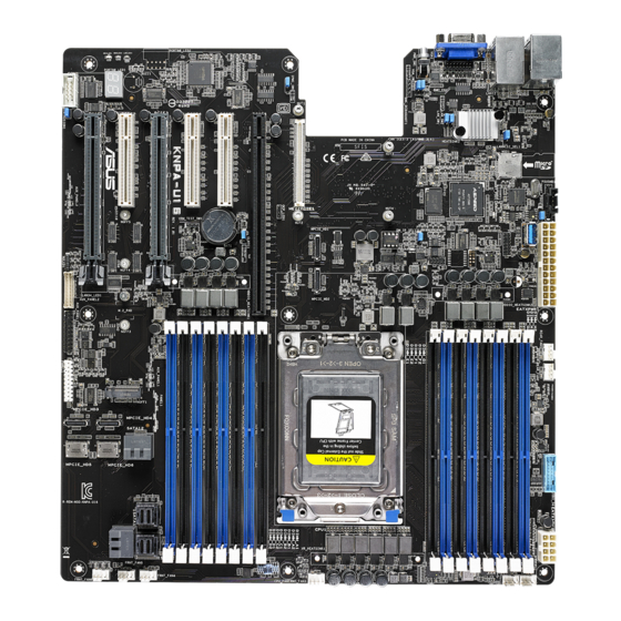
Page 16: Motherboard Layout
2.2.3 Motherboard layout Chapter 2: Hardware Information... - Page 17 2-28 AUX_PANEL2) Hard disk activity LED connector (4-pin HDLED1) 2-29 LAN Activity LED connector (5-1 pin LAN34_LED1) 2-25 Chassis Intrusion connectors (2-pin INTRUSION) 2-30 Serial port connector (10-1 pin COM1) 2-24 Q-Code LEDs 2-21 Clear RTC RAM (3-pin CLRTC1) 2-15 Mezzanine PCIE card connectors (MEZZPCIE1) 2-31 VGA controller setting (3-pin VGA_SW1) 2-16 BMC Setting (3-pin BMC_EN1) 2-17 VGA connector (10-1 pin VGA_HDR1) 2-29 Trusted Platform Module connector (20-1 pin TPM1) 2-26 VPP_I2C1 connector (10-1 pin VPP_I2C1) 2-33 DMLAN setting (3-pin DM_IP_EN1) 2-17 OCP LAN Activity LED connector (4-1 pin OCP_LED1) 2-32 KNPA-U16...
-
Page 18: Central Processing Unit (Cpu)
Central Processing Unit (CPU) The motherboard comes with a surface mount Socket SP3 designed for the AMD EPYC™ 7000 Series. • Upon purchase of the motherboard, ensure that the PnP cap is on the socket and the socket contacts are not bent. Contact your retailer immediately if the PnP cap is missing, or if you see any damage to the PnP cap/socket contacts/motherboard components. ASUS will shoulder the cost of repair only if the damage is shipment/ transit-related. • Keep the cap after installing the motherboard. ASUS will process Return Merchandise Authorization (RMA) requests only if the motherboard comes with the cap on the Socket SP3. • The product warranty does not cover damage to the socket contacts resulting from incorrect CPU installation/removal, or misplacement/loss/incorrect removal of the PnP cap. - Page 19 Loosen each screw one by one in the sequence shown on the socket to open the load plate. Slightly lift open the rail frame. Load plate Rail frame External cap Slide the external cap out of the rail frame. External cap Rail frame PnP cap KNPA-U16...
- Page 20 Slide the carrier frame with CPU into the rail frame, then remove the PnP cap. Carrier frame with CPU The carrier frame with CPU fits in only one correct orientation. DO NOT force Rail frame the carrier frame with CPU into the rail frame. PnP cap Gently push the rail frame just enough to let it sit on top of the CPU socket. Carrier frame with CPU Close the load plate just enough to let it sit on top of the CPU, then secure each screw one by one in the sequence shown on the socket to completely secure the load plate.
- Page 21 Twist each of the four screws with a screwdriver just enough to attach the heatsink to the motherboard. When the four screws are attached, tighten them one by one in a diagonal sequence to complete the installation. The heatsink screws are T20 models. A torque value of 12 inch-lbf is recommended. KNPA-U16...
-
Page 22: System Memory
System memory 2.4.1 Overview The motherboard comes with sixteen (16) Double Data Rate 4 (DDR4) Dual Inline Memory Modules (DIMM) sockets. The figure illustrates the location of the DDR4 DIMM sockets: 2.4.2 Memory Configurations You may install 32GB, 16GB, 8GB, 4GB RDIMM, 64GB, 32GB LRDIMM, or 128GB, 64GB LRDIMM 3DS into the DIMM sockets using the memory configurations in this section. Memory configurations DIMM 1 DIMM 2 DIMMs 4 DIMMs 6 DIMMs 8 DIMMs 10 DIMMs P 12 DIMMs 14 DIMMs... -
Page 23: Installing A Dimm On A Single Clip Dimm Socket
Always insert the DIMM into the socket vertically to prevent DIMM notch damage. Removing a DIMM from a single clip DIMM socket Press the retaining clip outward to unlock the DIMM. Remove the DIMM from the socket. Support the DIMM lightly with your fingers when pressing the retaining clips. The DIMM might get damaged when it flips out with extra force. KNPA-U16 2-11... -
Page 24: Expansion Slots
Expansion slots In the future, you may need to install expansion cards. The following subsections describe the slots and the expansion cards that they support. Ensure to unplug the power cord before adding or removing expansion cards. Failure to do so may cause you physical injury and damage motherboard components. 2.5.1 Installing an expansion card To install an expansion card: Before installing the expansion card, read the documentation that came with it and make the necessary hardware settings for the card. -
Page 25: Interrupt Assignments
2.5.3 Interrupt assignments Standard Interrupt assignments Priority Standard function System Timer Keyboard Controller Programmable Interrupt Communications Port (COM1) System CMOS/Real Time Clock ACPI Mode when used IRQ Holder for PCI Steering IRQ Holder for PCI Steering PS/2 Compatible Mouse Port Numeric Data Processor * These IRQs are usually available for ISA or PCI devices. KNPA-U16 2-13... - Page 26 No.(Slot location) Short Description PCIE6 PCI-E x24 (x16 Gen3 link) PCIE5 PCI-E x8 (x4 Gen3 link) PCIE4 PCI-E x8 (x4 Gen3 link) PCIE3 PCI-E x16 (x16 Gen3 link)* PCIE2 PCI-E x8 (x4 Gen3 link) PCIE1 PCI-E x16 (x16 Gen3 link) * When Slot Location 2 is occupied, Slot Location 3 will switch to PCIe 3.0 x8 link. Chapter 2: Hardware Information 2-14...
-
Page 27: Jumpers
To erase the RTC RAM: Turn OFF the computer and unplug the power cord. Move the jumper cap from the default pins 1–2 to pins 2–3. Keep the cap on pins 2–3 for about 5 to 10 seconds, then move the cap back to pins 1–2. Plug the power cord and turn ON the computer. Hold down the <Del> key during the boot process and enter BIOS setup to re- enter data. DO NOT remove the cap on CLRTC jumper default position except when clearing the RTC RAM. Removing the cap will cause system boot failure! If the steps above do not help, remove the onboard battery and move the jumper again to clear the CMOS RTC RAM data. After the CMOS clearance, reinstall the battery. KNPA-U16 2-15... - Page 28 VGA controller setting (3-pin VGA_SW1) This jumper allows you to enable or disable the onboard VGA controller. Set to pins 1–2 to activate the VGA feature. LAN controller settings (3-pin LAN_SW1-2) These jumpers allow you to enable or disable the onboard LAN_SW1 or LAN_SW2. Set to pins 1-2 to activate the Gigabit LAN feature. Chapter 2: Hardware Information 2-16...
- Page 29 BMC Setting (3-pin BMC_EN1) This jumper allows you to enable or disable the Baseboard Management Controller (ASMB9). DMLAN setting (3-pin DM_IP_EN1) This jumper allows you to select the DMLAN setting. Set to pins 2-3 to force the DMLAN IP to static mode (IP=10.10.10.10, submask=255.255.255.0). KNPA-U16 2-17...
- Page 30 LANNCSI setting (3-pin LANNCSI_SEL1) This jumper allows you to select which LAN NCSI to function. Smart Ride Through (SmaRT) setting (3-pin SMART_PSU1) This jumper allows you to enable or disable the Smart Ride Through (SmaRT) function. This feature is enabled by default. Set to pins 2-3 to disable it. When enabled, SmaRT allows uninterrupted operation of the system during an AC loss event. Chapter 2: Hardware Information 2-18...
-
Page 31: Onboard Leds
The motherboard comes with a standby power LED. The green LED lights up to indicate that the system is ON, in sleep mode, or in soft-off mode. This is a reminder that you should shut down the system and unplug the power cable before removing or plugging in any motherboard component. The illustration below shows the location of the onboard LED. BMC LED (BMCLED1) The BMC LED lights up to indicate that the on-board BMC is functional. This LED functions only when you enable ASUS ASMB9. KNPA-U16 2-19... - Page 32 Location LED (LOCLED1) This onboard LED lights up when the Location button on the server is pressed or when triggered by a system management software. The Location LED helps visually locate and quickly identify the server in error on a server rack. Message LED (MESLED1) This onboard LED lights up to red when there is a BMC event log is generated.
- Page 33 Hard disk activity LED (HDDLED1) This LED is for the storage devices connected to the onboard SATA, or SATA/SAS add-on card. The read or write activities of any device connected to the onboard SATA, or SATA/SAS add-on card causes the rear panel LED to light up. Q-Code LEDs The Q-Code LED design provides you with a 2-digit error code that displays the system status. Refer to the Q-Code table on the next page for details. • The Q-Code LEDs provide the most probable cause of an error code as a starting point for troubleshooting. The actual cause may vary from case to case. • Please refer to the Q-Code table in the Appendix section for more details. KNPA-U16 2-21...
-
Page 34: Connectors
Connectors 2.8.1 Rear panel connectors RJ-45 port for iKVM. This RJ-45 port functions only when you install ASMB9 management card. RJ-45 port for LAN 1 and LAN 2. This port allows Gigabit connection to a Local Area Network (LAN) through a network hub. Refer to the table below for the LAN port LED indications. -
Page 35: Internal Connectors
ATA signal cables for Serial ATA drives (SATA 1 connector is used for the optical drive by default). The actual data transfer rate depends on the speed of Serial ATA hard disks installed. Power Supply SMBus connector (5-pin PSUSMB1) This connector allows you to connect SMBus (System Management Bus) to the PSU (power supply unit) to read PSU information. Devices communicate with an SMBus host and/or other SMBus devices using the SMBus interface. This connector functions only when you enable ASUS ASMB9. KNPA-U16 2-23... - Page 36 USB 3.0 connector (20-1 pin USB3_34; 4-pin Type-A USB3_4) The 20-1 pin connector allows you to connect a USB 3.0 module for additional USB 3.0 front or rear panel ports. The 4-pin USB (Universal Serial Bus) Type-A port is available for connecting USB 3.0 devices. Serial port connector (10-1 pin COM1) This connector is for the serial COM port. Connect the serial port module cable to one of these connectors, then install the module to a slot opening at the back of the system chassis. The COM module is purchased separately. Chapter 2: Hardware Information 2-24...
- Page 37 CPU, front, and rear fan connectors (4-pin FRNT_FAN1-7, REAR_FAN1-2) The fan connectors support cooling fans. Connect the fan cables to the fan connectors on the motherboard, ensuring that the black wire of each cable matches the ground pin of the connector. • DO NOT forget to connect the fan cables to the fan connectors. Insufficient air flow inside the system may damage the motherboard components. • These are not jumpers! DO NOT place jumper caps on the fan connectors! • All fans feature the ASUS Smart Fan technology. LAN Activity LED connector (5-1 pin LAN34_LED1) These leads are for 10G LAN activity LEDs on the front panel. Connect the LAN LED cable to the backplane for LAN activity indication. KNPA-U16 2-25...
- Page 38 Trusted Platform Module connector (20-1 pin TPM1) This connector supports a Trusted Platform Module (TPM) system, which can securely store keys, digital certificates, passwords, and data. A TPM system also helps enhance network security, protects digital identities, and ensures platform integrity. ATX power connectors (24-pin EATXPWR1, 8-pin EATX12V1) These connectors are for the ATX power supply plugs. The power supply plugs are designed to fit these connectors in only one orientation. Find the proper orientation and push down firmly until the connectors completely fit. • DO NOT forget to connect the 24-pin and the 8-pin power plugs; otherwise, the system will not boot up. • Use of a power supply unit (PSU) with a higher power output is recommended when configuring a system with more power-consuming devices. The system may become unstable or may not boot up if the power is inadequate.
-
Page 39: System Panel Connector 20-1 Pin Panel
Pressing the power switch for more than four seconds while the system is ON turns the system OFF. Reset button (2-pin RESET) This 2-pin connector is for the chassis-mounted reset button for system reboot without turning off the system power. KNPA-U16 2-27... - Page 40 Auxiliary panel connector (20-2 pin AUX_PANEL1, 20-pin AUX_PANEL2) This connector is for additional front panel features including front panel SMB, locator LED and switch, chassis intrusion, and LAN LEDs. Front panel SMB (6-1 pin FPSMB) These leads connect the front panel SMBus cable. LAN activity LED (2-pin LAN1_LED, LAN2_LED) These leads are for the Gigabit LAN activity LEDs on the front panel. Locator LED (2-pin LOCATORLED1, LOCATORLED2) These leads are for the locator LED1 and LED2 on the front panel. Connect the Locator LED cables to these 2-pin connector.
- Page 41 This LED connector is for the storage add-on card cable connected to the SATA or SAS add-on card. The read or write activities of any device connected to the SATA or SAS add-on card causes the front panel LED to light up. KNPA-U16 2-29...
- Page 42 Chassis Intrusion connectors (2-pin INTRUSION) This lead is for the intrusion detection feature for chassis with intrusion sensor or microswitch. When you remove any chassis component, the sensor triggers and sends a high level signal to these leads to record a chassis intrusion event. The default setting is short CASEOPEN and GND pin by jumper cap to disable the function. OCUPCIE connectors (MPCIE_HD1-6) Connects the PCIE signal to the NVME port on the backplane.
- Page 43 M.2 (NGFF) connectors (NGFF1) This connector allows you to install M.2 devices. This connector supports type 2242/2260/2280/22110 devices on both PCI-E and SATA interface. The M.2 (NGFF) device is purchased separately. Mezzanine PCIE card connectors (MEZZPCIE1) The MEZZPCIE1 connector supports Open Compute Project (OCP) cards. KNPA-U16 2-31...
- Page 44 OCP LAN Activity LED connector (4-1 pin OCP_LED1) OCP LAN LED connector supports OCP LAN card Active LED. Micro SD card slot (MSD1) Your motherboard supports SD Memory Card v2.00 (SDHC) / v3.00 (SDXC). Disconnect all power (including redundant PSUs) from the existing system before you add or remove a Memory Card, then reboot the system to access the Memory Card. • This Micro SD card slot functions only when you enable ASUS ASMB9. • Some memory cards may not be compatible with your motherboard. Ensure that you use only compatible memory cards to prevent loss of data, damage to your device, or memory card, or both. Chapter 2: Hardware Information 2-32...
- Page 45 Mini-SAS HD connectors (ISATA1-2) This motherboard comes with mini Serial Attached SCSI (SAS) HD connectors, the storage technology that supports Serial ATA. Each connector supports up to four devices. VPP_I2C1 connector (10-1 pin VPP_I2C1) This connector is used for the Intel VMD function and sensor readings. KNPA-U16 2-33...
- Page 46 Chapter 2: Hardware Information 2-34...
-
Page 47: Chapter 3: Powering Up
Chapter 3: Powering Up Powering Up This chapter describes the power up sequence, and ways of shutting down the system. -
Page 48: Starting Up For The First Time
Starting up for the first time After making all the connections, replace the system case cover. Be sure that all switches are off. Connect the power cord to the power connector at the back of the system chassis. Connect the power cord to a power outlet that is equipped with a surge protector. Turn on the devices in the following order: Monitor External storage devices (starting with the last device on the chain) -
Page 49: Powering Off The Computer
While the system is ON, press the power switch for less than four seconds to put the system to sleep mode or to soft-off mode, depending on the BIOS setting. Pressing the power switch for more than four seconds lets the system enter the soft-off mode regardless of the BIOS setting. KNPA-U16... - Page 50 Chapter 3: Powering Up...
-
Page 51: Chapter 4: Bios Setup
Chapter 4: BIOS Setup BIOS Setup This chapter tells how to change the system settings through the BIOS Setup menus. Detailed descriptions of the BIOS parameters are also provided. -
Page 52: Managing And Updating Your Bios
BIOS in the future. Copy the original motherboard BIOS using the BUPDATER utility. 4.1.1 ASUS CrashFree BIOS 3 utility The ASUS CrashFree BIOS 3 is an auto recovery tool that allows you to restore the BIOS file when it fails or gets corrupted during the updating process. You can update a corrupted BIOS file using a USB flash drive that contains the updated BIOS file. -
Page 53: Asus Ez Flash Utility
4.1.2 ASUS EZ Flash Utility The ASUS EZ Flash Utility feature allows you to update the BIOS without having to use a DOS-based utility. Before you start using this utility, download the latest BIOS from the ASUS website at www.asus.com. To update the BIOS using EZ Flash Utility: Insert the USB flash disk that contains the latest BIOS file into the USB port. Enter the BIOS setup program. Go to the Tool menu then select ASUS EZ Flash Utility. -
Page 54: Bupdater Utility
The BUPDATER utility allows you to update the BIOS file in the DOS environment using a bootable USB flash disk drive with the updated BIOS file. Updating the BIOS file To update the BIOS file using the BUPDATER utility: Visit the ASUS website at www.asus.com and download the latest BIOS file for the motherboard. Save the BIOS file to a bootable USB flash disk drive. Copy the BUPDATER utility (BUPDATER.exe) from the ASUS support website at https://www.asus.com/support to the bootable USB flash disk drive you created earlier. Boot the system in DOS mode, then at the prompt, type: BUPDATER /i[filename].CAP where [filename] is the latest or the original BIOS file on the bootable USB flash disk drive, then press <Enter>. A:\>BUPDATER /i[file name].CAP... - Page 55 The utility verifies the file, then starts updating the BIOS file. ASUS Tek. EzFlash Utility Current Platform New Platform Platform : KNPA-U16 Platform : KNPA-U16 Version : 0201 Version : 0207 Build date: 12/04/2018 Build date: 01/05/2018 Start Programming Flash. DO NOT SHUTDOWN THE SYSTEM!!! Write DO NOT shut down or reset the system while updating the BIOS to prevent system boot failure! The utility returns to the DOS prompt after the BIOS update process is completed.
-
Page 56: Bios Setup Program
If the system becomes unstable after changing any BIOS settings, load the default settings to ensure system compatibility and stability. Press <F5> and select Yes to load the BIOS default settings. • The BIOS setup screens shown in this section are for reference purposes only, and may not exactly match what you see on your screen. • Visit the ASUS website (www.asus.com) to download the latest BIOS file for this motherboard. Chapter 4: BIOS Setup... -
Page 57: Bios Menu Screen
For changing the security settings Boot For changing the system boot configuration Tool For configuring options for special functions Save & Exit For selecting the exit options AMD CBS For configuring AMD CBS settings Event Logs For changing the event log settings Server Mgmt For changing the Server Mgmt settings To select an item on the menu bar, press the right or left arrow key on the keyboard until the desired item is highlighted. KNPA-U16... -
Page 58: Menu Items
4.2.3 Menu items The highlighted item on the menu bar displays the specific items for that menu. For example, selecting Main shows the Main menu items. The other items (such as Advanced) on the menu bar have their respective menu items. 4.2.4 Submenu items A solid triangle before each item on any menu screen means that the item has a submenu. To display the submenu, select the item then press <Enter>. -
Page 59: Main Menu
Main menu When you enter the BIOS Setup program, the Main menu screen appears. The Main menu provides you an overview of the basic system information, and allows you to set the system date, time, language, and security settings. 4.3.1 System Date [Day xx/xx/xxxx] Allows you to set the system date. 4.3.2 System Time [xx:xx:xx] Allows you to set the system time. KNPA-U16... -
Page 60: Advanced Menu
Advanced menu The Advanced menu items allow you to change the settings for the CPU and other system devices. Take caution when changing the settings of the Advanced menu items. Incorrect field values can cause the system to malfunction. NVMe Hotplug [Disabled] [Disabled] Disables NVMe Hotplug. [Enabled] Enables NVMe Hotplug. Chapter 4: BIOS Setup 4-10... -
Page 61: Trusted Computing
4.4.1 Trusted Computing Configuration Security Device Support [Enabled] Allows you to enable or disable the BIOS support for security device. Configuration options: [Disabled] [Enabled] 4.4.2 PSP Firmware Versions This page displays the PSP firmware versions. KNPA-U16 4-11... -
Page 62: Apm
4.4.3 Allows you to configure the Advance Power Management (APM) settings. Restore AC Power Loss [Last State] When set to [Power Off], the system goes into off state after an AC power loss. When set to [Power On], the system will reboot after an AC power loss. When set to [Last State], the system goes into either off or on state, whatever the system state was before the AC power loss. Configuration options: [Power Off] [Power On] [Last State] Power On By PCIE [Disabled] [Disabled] Disables the PCIE devices to generate a wake event. [Enabled] Enables the PCIE devices to generate a wake event. Power On By RTC [Disabled] [Disabled] Disables RTC to generate a wake event. [Enabled] W hen set to [Enabled], the items RTC Alarm Date (Days) and Hour/Minute/Second will become user-configurable with set values. Chapter 4: BIOS Setup 4-12... -
Page 63: Smart Settings
Smart Settings SMART Self Test [Enabled] Allows you to run SMART Self Test on all HDDs during POST. Configuration options: [Disabled] [Enabled] 4.4.5 NCT6793D Super IO Configuration Serial Port 1 Configuration Allows you to set the parameters of Serial Port 1. Serial Port [Enabled] Allows you to enable or disable Serial Port. Configuration options: [Disabled] [Enabled] KNPA-U16 4-13... -
Page 64: Onboard Lan Configuration
4.4.6 Onboard LAN Configuration Intel LAN1 Enable [Enabled] Allows you to enable or disable the Intel LAN. Configuration options: [Disabled] [Enabled] The following items appear only when Intel LAN1 Enable is set to [Enabled]. Intel LAN 1 ROM Type [PXE] Allows you to select the Intel LAN ROM type. Configuration options: [PXE] [iSCSI] [Disabled] Intel LAN2 Enable [Enabled] Allows you to enable or disable the Intel LAN. Configuration options: [Disabled] [Enabled] The following items appear only when Intel LAN2 Enable is set to [Enabled]. Intel LAN 2 ROM Type [Disabled] Allows you to select the Intel LAN ROM type. -
Page 65: Serial Port Console Redirection
Allows you to set the terminal type. [VT100] ASCII char set. [VT100+] Extends VT100 to support color, function keys, etc. [VT-UTF8] Uses UTF8 encoding to map Unicode chars onto 1 or more bytes. [ANSI] Extended ASCII char set. Bits per second [57600] Selects serial port transmission speed. The speed must be matched on the other side. Long or noisy lines may require lower speeds. Configuration options: [9600] [19200] [38400] [57600] [115200] Data Bits [8] Configuration options: [7] [8] KNPA-U16 4-15... - Page 66 Parity [None] A parity bit can be sent with the data bits to detect some transmission errors. [Mark] and [Space] parity do not allow for error detection. [None] None [Even] parity bit is 0 if the num of 1’s in the data bits is even [Odd] parity bit is 0 if num of 1’s in the data bits is odd [Mark] parity bit is always 1 [Space] parity bit is always 0 Stop Bits [1] Stop bits indicate the end of a serial data packet. (A start bit indicates the beginning.) The standard setting is 1 stop bit. Communication with slow devices may require more than 1 stop bit. Configuration options: [1] [2] Flow Control [Hardware RTS/CTS] Flow control can prevent data loss from buffer overflow. When sending data, if the receiving buffers are full, a “stop” signal can be sent to stop the data flow. Once the buffers are empty, a “start” signal can be sent to re-start the flow. Hardware flow control...
-
Page 67: Cpu Configuration
Flow Control [None] Microsoft Windows Emergency Management Services (EMS) allow for remote management of a Windows Server OS through a serial port. Configuration options: [None] [Hardware RTS/CTS] [Software Xon/Xoff] 4.4.8 CPU Configuration This page displays the CPU node information. SVM Mode [Enabled] Allows you to enable or disable SVM Mode. Configuration options: [Disabled] [Enabled] SMEE [Enabled] Allows you to enable or disable SMEE. Configuration options: [Disabled] [Enabled] KNPA-U16 4-17... -
Page 68: Pci Subsystem Settings
4.4.9 PCI Subsystem Settings Allows you to configure PCI, PCI-X, and PCI Express Settings. VGA Palette Snoop [Disabled] This option enables or disables VGA Palette Registers Snooping. Configuration options: [Disabled] [Enabled] VGA Priority [Offboard Device] This option allows you to select the priority of the VGA. Configuration options: [Offboard Device] [Onboard Device] Load RT32 Image [Disabled] This option enables or disables RT32 Image Loading. Configuration options: [Disabled] [Enabled] Above 4G Decoding [Disabled] Allows you to enable or disable 64-bit capable devices to be decoded in above 4G address... -
Page 69: Network Stack Configuration
Configuration options: [Disabled] [Enabled] Ipv6 PXE Support [Disabled] Enables or disables the Ipv6 PXE Boot Support. If disabled, Ipv6 PXE boot option will not be created. Configuration options: [Disabled] [Enabled] Ipv6 HTTP Support [Disabled] Enables or disables the Ipv6 HTTP Boot Support. If disabled, Ipv6 HTTP boot option will not be created. Configuration options: [Disabled] [Enabled] IP6 Configuration Policy [Automatic] This item allows you to st the IP6 Configuration policy. Configuration options: [Automatic] [Manual] PXE boot wait time [0] Wait time to press ESC key to abort the PXE boot. Media detect time [1] Wait time (in seconds) to detect media. KNPA-U16 4-19... -
Page 70: Csm Configuration
4.4.11 CSM Configuration CSM Support [Enabled] This option allows you to enable or disable CSM Support. Configuration options: [Disabled] [Enabled] The following item appears only when CSM Support is set to [Enabled]. GateA20 Active [Upon Request] This allows you to set the GA20 option. Configuration options: [Upon Request] [Always] Option ROM Messages [Force BIOS] This allows you to set the display mode for option ROM. -
Page 71: Nvme Configuration
4.4.12 NVMe Configuration This page will display the NVMe controller and drive information. 4.4.13 SATA Configuration This page will display the SATA controller and drive information. KNPA-U16 4-21... -
Page 72: Usb Configuration
4.4.14 USB Configuration Legacy USB Support [Enabled] Allows you to enable or disable Legacy USB device support. Configuration options: [Enabled] [Disabled] [Auto] XHCI Hand-off [Enabled] Allows you to enable or disable workaround for OSes without XHCI hand-off support. The XHCI ownership change should be claimed by XHCI driver. Configuration options: [Enabled] [Disabled] USB Mass Storage Driver Support [Enabled] Allows you to enable or disable the USB Mass Storage driver support. Configuration options: [Disabled] [Enabled] Port 60/64 Emulation [Enabled] Allows you to enable or disable I/O port 60h/64h emulation support. This should be enabled for the complete keyboard legacy support for non-USB aware OSes. -
Page 73: Iscsi Configuration
Allows you to select time-out value for USB mass storage device Start Unit command. Configuration options: [10 sec] [20 sec] [30 sec] [40 sec] Device power-up delay [Auto] Allows you to select maximum time the device will take before it properly reports itself to the Host Controller. Configuration options: [Auto] [Manual] Mass Storage Devices AMI Virtual CDROM0-2 / Floppy / HDisk0 1.00 [Auto] Allows you to select the mass storage device emulation type. Configuration options: [Auto] [Floppy] [Forced FDD] [Hard Disk] [CD-ROM] 4.4.15 iSCSI Configuration Allows you to configure the iSCSi parameters. KNPA-U16 4-23... -
Page 74: Chipset Menu
Chipset menu The Chipset menu items allow you to change the Chipset settings. SMT Mode [Auto] Allows you to select the simultaneous multithreading mode. Configuration options: [Auto] [Off] PCIe Link Training Type [1 Step] Allows you to select the PCIe training in 1 or 2 steps. Configuration options: [1 Step] [2 Step] North Bridge Memory Configuration... -
Page 75: Security Menu
Mode state. Administrator Password To set an administrator password: Select the Administrator Password item and press <Enter>. From the Create New Password box, key in a password, then press <Enter>. Confirm the password when prompted. To change an administrator password: Select the Administrator Password item and press <Enter>. From the Enter Current Password box, key in the current password, then press <Enter>. From the Create New Password box, key in a new password, then press <Enter>. Confirm the password when prompted. To clear the administrator password, follow the same steps as in changing an administrator password, but press <Enter> when prompted to create/confirm the password. KNPA-U16 4-25... - Page 76 User Password To set a user password: Select the User Password item and press <Enter>. From the Create New Password box, key in a password, then press <Enter>. Confirm the password when prompted. To change a user password: Select the User Password item and press <Enter>. From the Enter Current Password box, key in the current password, then press <Enter>. From the Create New Password box, key in a new password, then press <Enter>. Confirm the password when prompted. To clear a user password: Select the Clear User Password item and press <Enter>. Select Yes from the Warning message window then press <Enter>.
- Page 77 This item will allow the image to run in Secure Boot mode. Save All Secure Boot Variables This item will ask you if you want to save all secure boot variables. Select Yes if you want to save all secure boot variables, otherwise select No. Platform Key (PK) / Key Exchange Key (KEK) / Authorized Signatures (DB) / Forbidden Signatures (DBX) / Authorized TimeStamps (DBT) / OsRecovery Signatures Configuration options: [Erase] [Set New] [Save to File] KNPA-U16 4-27...
-
Page 78: Boot Menu
These items specify the boot device priority sequence from the available devices. The number of device items that appears on the screen depends on the number of devices installed in the system. • To select the boot device during system startup, press <F8> when ASUS Logo appears. • To access Windows OS in Safe Mode, please press <F8> after POST. Chapter 4: BIOS Setup... -
Page 79: Tool Menu
IPMI HWM Allows you to run the IPMI hardware monitor. Start EZ Flash Allows you to run ASUS EZ Flash BIOS ROM Utility when you press <Enter>. Refer to the ASUS EZ Flash Utility section for details. Save & Exit menu The Exit menu items allow you to save or discard your changes to the BIOS items. - Page 80 Pressing <Esc> does not immediately exit this menu. Select one of the options from this menu or <F10> from the legend bar to exit. Save Changes and Exit Exit system setup after saving the changes. Discard Changes and Exit Exit system setup without saving any changes. Save Changes and Reset Rest system setup after saving the changes.
-
Page 81: Amd Cbs Menu
This option allows you to control IO based C-state generation and DF c-states. Configuration options: [Disabled] [Enabled] [Auto] Streaming Stores Control [Auto] This option allows you to enable or disable the streaming stores functionality. Configuration options: [Disabled] [Enabled] [Auto] Prefetcher settings L1 Stream HW Prefetcher [Auto] This option allows you to enable or disable L1 Stream HW Prefetcher. Configuration options: [Disabled] [Enabled] [Auto] L2 Stream HW Prefetcher [Auto] This option allows you to enable or disable L2 Stream HW Prefetcher. Configuration options: [Disabled] [Enabled] [Auto] KNPA-U16 4-31... -
Page 82: Df Common Options
4.10.2 DF Common Options Memory interleaving [Auto] This option allows you to control fabric level memory interleaving. Configuration options: [None] [Channel] [Die] [Socket] [Auto] Memory interleaving size [Auto] This option allows you to control the memory interleaving size. Configuration options: [256 Bytes] [512 Bytes] [1 KB] [2 KB] [Auto] 4.10.3 UMC Common Option DDR4 Common Options DRAM Timing Configuration This option allows you to set memory overclock settings. Read the disclaimer and select I Accept to continue. - Page 83 This option allows you to set the DRAM ECC Symbol Size. Configuration options: [Auto] [x4] [x8] DRAM ECC Enable [Auto] This option allows you to enable or disable DRAM ECC. Configuration options: [Disabled] [Enabled] [Auto] DRAM Memory Mapping Chipselect Interleaving [Auto] This option allows you to interleave memory blocks across DRAM chip selects for node 0. Configuration options: [Disabled] [Auto] BankGroupSwap [Auto] This option allows you to enable or disable BankGroupSwap. Configuration options: [Disabled] [Enabled] [Auto] KNPA-U16 4-33...
-
Page 84: Nbio Common Options
4.10.4 NBIO Common Options NB Configuration IOMMU [Enabled] This option allows you to enable or disable IOMMU. Configuration options: [Disabled] [Enabled] [Auto] Concurrent Training [Auto] This option allows you to enable or disable Concurrent Training. Configuration options: [False] [True] [Auto] NBIO Internal Poison Consumption [Auto] This option allows you to enable or disable NBIO Internal Poison Consumption. Configuration options: [Disabled] [Enabled] [Auto] NBIO RAS Control [Auto] This option allows you to enable or disable NBIO RAS Control. - Page 85 Disable BridgeDis [Disabled] This option allows you to enable or disable BridgeDis update based on sideband. Configuration options: [Disabled] [Enabled] [Auto] Disable irq polling [Disabled] This option allows you to enable or disable irq polling. Configuration options: [Disabled] [Enabled] [Auto] IRQ sets BridgeDis [Disabled] This option allows you to enable or disable IRQ sets BridgeDis. Configuration options: [Disabled] [Enabled] [Auto] KNPA-U16 4-35...
-
Page 86: Event Logs Menu
4.11 Event Logs menu The Event Logs menu items allow you to change the event log settings and view the system event logs. 4.11.1 Change Smbios Event Log Settings Press <Enter> to change the Smbios Event Log configuration. All values changed here do not take effect until computer is restarted. Enabling/Disabling Options Smbios Event Log [Enabled] Change this to enable or disable all features of Smbios Event Logging during boot. Configuration options: [Disabled] [Enabled] Erasing Settings Erase Event Log [No] Choose options for erasing Smbios Event Log. Erasing is done prior to any logging activation during reset. Configuration options: [No] [Yes, Next reset] [Yes, Every reset] When Log is Full [Do Nothing] Choose options for reacting to a full Smbios Event Log. Configuration options: [Do Nothing] [Erase Immediately] Smbios Event Log Standard Settings Log System Boot Event [Disabled]... -
Page 87: Server Mgmt Menu
Allows you to configure the length fo the OS Boot Watchdog Timer. Configuration options: [5 minutes] [10 minutes] [15 minutes] [20 minutes] OS Wtd Timer Policy [Reset] This item allows you to configure the how the system should respond if the OS Boot Watch Timer expires. Configuration options: [Do Nothing] [Reset] [Power Down] System Event Log Allows you to change the SEL event log configuration. SEL Components [Enabled] This option allows you to enable or disable SEL Components. Configuration options: [Disabled] [Enabled] The following items is configurable only when the SEL Components is set to [Enabled]. Erase SEL [No] Allows you to choose options for erasing SEL. Configuration options: [No] [Yes, On next reset] [Yes, On every reset] When SEL is Full [Do Nothing] Allows you to choose options for reactions to a full SEL. Configuration options: [Do Nothing] [Erase Immediately] KNPA-U16 4-37... - Page 88 Chapter 4: BIOS Setup 4-38...
-
Page 89: Chapter 5: Driver Installation
Chapter 5: Driver Installation Driver Installation This chapter provides the instructions for installing the necessary drivers for different system components in the ® Windows Operating System. -
Page 90: Management Applications And Utilities Installation
The contents of the support DVD are subject to change at any time without notice. Visit the ASUS website (www.asus.com) for the latest updates on software and utilities. - Page 91 The Drivers Menu shows the available device drivers if the system detects installed devices. Install the necessary drivers to activate the devices. 5.2.2 Utilities menu tab The Utilities menu displays the software applications and utilities that the motherboard supports. KNPA-U16...
- Page 92 You need an internet browser installed in your OS to view the User Guide. 5.2.4 Contact information menu The Contact menu displays the ASUS contact information, e-mail addresses, and useful links if you need more information or technical support for your motherboard. Chapter 5: Driver Installation...
-
Page 93: Amd Chipset Device Software Installation
ASSETUP.EXE from the BIN folder. Double-click the ASSETUP.EXE to run the support DVD. Click the item AMD Software from the menu. The AMD Software window appears. Click Accept and Install to start the installation, and follow the onscreen instructions to complete the setup process. KNPA-U16... -
Page 94: Installing The Intel ® I350-Am2 Gigabit Adapters Driver
® Installing the Intel I350-AM2 Gigabit Adapters driver ® This section provides the instructions on how to install the Intel I350-AM2 Gigabits Adapter Driver on the system. ® ® To install the Intel I350-AM2 Gigabit Adapters Driver on the Windows operating system: Restart the computer. - Page 95 Click Install to start the installation. When the installation is done, press Finish to complete the installation. KNPA-U16...
-
Page 96: Vga Driver Installation
VGA driver installation This section provides the instructions on how to install the ASPEED Video Graphics Adapter (VGA) driver. ® You need to manually install the ASPEED VGA driver on a Windows operating system. To install the ASPEED VGA driver: Restart the computer, and then log on with Administrator privileges. - Page 97 Click Install to start the installation process. Click Finish to complete the installation. KNPA-U16...
- Page 98 Chapter 5: Driver Installation 5-10...
-
Page 99: Appendix
Appendix Appendix This appendix includes additional information that you may refer to when configuring the motherboard. -
Page 100: Knpa-U16 Block Diagram
KNPA-U16 block diagram Appendix... -
Page 101: Q-Code Table
Recovery condition triggered by user (Forced recovery) Recovery process started Recovery firmware image is found Recovery firmware image is loaded F5 – F7 Reserved for future AMI progress codes Recovery PPI is not available Recovery capsule is not found (continued on the next page) KNPA-U16... - Page 102 Code Description Invalid recovery capsule FB – FF Reserved for future AMI error codes DXE Core is started NVRAM initialization Installation of the PCH Runtime Services 63 – 67 CPU DXE initialization is started PCI host bridge initialization System Agent DXE initialization is started System Agent DXE SMM initialization is started 6B –...
- Page 103 System is waking up from the S3 sleep state System is waking up from the S4 sleep state System has transitioned into ACPI mode. Interrupt controller is in PIC mode. System has transitioned into ACPI mode. Interrupt controller is in APIC mode. KNPA-U16...
-
Page 104: Notices
Notices Federal Communications Commission Statement This device complies with Part 15 of the FCC Rules. Operation is subject to the following two conditions: • This device may not cause harmful interference, and • This device must accept any interference received including interference that may cause undesired operation. - Page 105 If you require assistance please call ASUS Customer Service 1300 2787 88 or visit us at https://www.asus.com/support.
-
Page 106: Simplified Eu Declaration Of Conformity
доступний на: www.asus.com/support Cijeli tekst EU izjave o sukladnosti dostupan je na: www.asus.com/support Türkçe AsusTek Computer Inc., bu aygıtın temel gereksinimlerle ve Čeština Společnost ASUSTeK Computer Inc. tímto prohlašuje, že toto ilişkili Yönergelerin diğer ilgili koşullarıyla uyumlu olduğunu beyan... -
Page 107: Asus Contact Information
ASUS contact information ASUSTeK COMPUTER INC. Address 4F, No. 150, Li-Te Rd., Peitou, Taipei 112, Taiwan Telephone +886-2-2894-3447 +886-2-2890-7798 Web site https://www.asus.com Technical Support Telephone +86-21-38429911 +86-21-58668722 ext: 9101 Online Support https://www.asus.com/support/Product/ContactUs/Services/ questionform/?lang=en ASUSTeK COMPUTER INC. (Taiwan) Address 4F, No. 150, Li-Te Rd., Peitou, Taipei 112, Taiwan... - Page 108 +1-510-608-4555 Web site https://www.asus.com/us/ Technical Support Support fax +1-812-284-0883 General support +1-812-282-2787 Online support https://www.asus.com/support/Product/ContactUs/Services/ questionform/?lang=en-us ASUS COMPUTER GmbH (Germany and Austria) Address Harkort Str. 21-23, 40880 Ratingen, Germany +49-2102-959911 Web site https://www.asus.com/de/ Technical Support Telephone +49-1805-010923 Support Fax +49-2102-959911 Online support https://www.asus.com/support/Product/ContactUs/Services/...
- Page 109 Web site https://www.asus.com/nl/ Technical Support Telephone +31-(0)591-5-70292 +31-(0)591-666853 E-mail advance.rma.eu@asus.com Online Support https://www.asus.com/support/Product/ContactUs/Services/ questionform/?lang=nl-nl ASUS Polska Sp. z o.o. (Poland) Address Ul. Postępu 6, 02-676 Warszawa, Poland Web site https://www.asus.com/pl/ Technical Support Telephone +48-225718033 Online Support https://www.asus.com/support/Product/ContactUs/Services/ questionform/?lang=pl-pl ASK-Service (Russia and CIS) г.Москва, ул.
- Page 110 A-12 Appendix...