Dell Equallogic PS6000 Hardware Maintenance
Storage arrays
Hide thumbs
Also See for Equallogic PS6000:
- Configuration manual (73 pages) ,
- Installation and setup manual (62 pages) ,
- Hardware manual (50 pages)
Table of Contents
Advertisement
Advertisement
Table of Contents

Related Manuals for Dell Equallogic PS6000


Summary of Contents for Dell Equallogic PS6000
- Page 1 Hardware Maintenance...
- Page 2 Copyright 2009 EqualLogic, Inc. All rights reserved. EqualLogic is a registered trademark. Dell is a trademark of Dell, Inc. All trademarks and registered trademarks mentioned herein are the property of their respective owners. Information in this document is subject to change without notice.
-
Page 3: Table Of Contents
Table of Contents Preface ........................v Audience ......................v Organization ....................v Documentation ....................vi Technical Support and Customer Service ............vi Warranty Information .................. viii 1 Basic Storage Array Information..............1-1 Array Front and Back Panels................ 1-1 Interpreting Operations Panel LEDs ............1-2 Using an Electrostatic Wrist Strap ............... 1-5 Shutting Down and Restarting an Array ............ - Page 4 PS6000 Hardware Maintenance Table of Contents 3. Inserting the Micro SD Card..............3-15 4 Maintaining Power Supply Modules............4-1 Interpreting the LEDs................... 4-1 Identifying Failures ..................4-1 Removing a Power Supply and Cooling Module......... 4-2 Installing a Power Supply and Cooling Module .......... 4-3 A Environmental, Power, and Other Specifications........A-1 Index......................Index-1...
-
Page 5: Preface
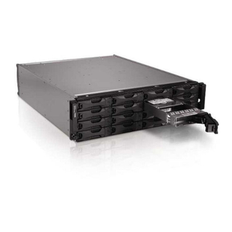
Preface This manual describes how to maintain the hardware for PS6000 storage arrays. Each array contains hot-swappable power supply and cooling modules, eight or sixteen RAID-protected disks, and dual hot-swappable control modules. With one or more PS Series arrays, you can create a PS Series group—a self- managing, iSCSI storage area network (SAN) that is affordable and easy to use, regardless of scale. -
Page 6: Documentation
Technical Support and Customer Service Dell’s support service is available to answer your questions about PS Series arrays. If you have an Express Service Code, have it ready when you call. The code helps Dell’s automated-support telephone system direct your call more... - Page 7 Contact Us 4. Select the appropriate service or support link based on your need. 5. Choose the method of contacting Dell that is convenient for you. Online Services You can learn about Dell products and services on the following websites: •...
-
Page 8: Warranty Information
PS6000 Hardware Maintenance Preface Warranty Information The PS6000 array warranty is included in the shipping box. For information about registering a warranty, visit support.dell.com/EqualLogic viii... -
Page 9: Basic Storage Array Information
1 Basic Storage Array Information This chapter includes basic information about PS6000 storage arrays. Array Front and Back Panels The front and back panels of a PS6000 array are shown in the following figures. Figure 1-1: PS6000 Front Panel The disk drives are accessible from the front. See Chapter 2 for detailed information about disk drives. -
Page 10: Interpreting Operations Panel Leds
PS6000 Hardware Maintenance Basic Array Information Figure 1-2: PS6000 Back Panel Table 1-1: Back Panel Detail Description Part Description Power supply and cooling modules. From left to right, they are numbered 1 and Control modules. From left to right, they are numbered 1 and 0. Operation panel LED. - Page 11 PS6000 Hardware Maintenance Basic Array Information Figure 1-3 shows the operations panel LEDs, which can alert you to errors and conditions that require your attention. Table 1-2 describes the LEDs. Report any serious problems to your array support provider. For information about other array LEDs, see Interpreting Disk LEDs on page 2-2, Interpreting Control Module LEDs on page 3-2, and Interpreting the LEDs on page 4-1.
- Page 12 PS6000 Hardware Maintenance Basic Array Information Table 1-2: Operations Panel Descriptions (Continued) Item Status Description No power or normal condition. Flashing orange One or more of the following has occurred: Warning • RAID set is degraded but still functioning. condition •...
-
Page 13: Using An Electrostatic Wrist Strap
PS6000 Hardware Maintenance Basic Array Information Table 1-2: Operations Panel Descriptions (Continued) Item Status Description This label contains the serial number for your array. If you contact your PS Series support provider, you may need to provide this number. Serial number label Using an Electrostatic Wrist Strap When handling the array chassis, disks, or control modules, you must use an... -
Page 15: Maintaining Disks
2 Maintaining Disks A PS6000 array includes up to 16 hot-swappable disks, either Serial Attached SCSI (SAS) disks or Serial ATA (SATA) disks. Disk maintenance topics apply to both SAS and SATA disks. Removing the Bezel To access the disks in a PS6000, you must remove the bezel. The bezel comes with a lock, which helps protect the disks from being tampered with or accidentally removed. -
Page 16: Interpreting Disk Leds
PS6000 Hardware Maintenance Maintaining Disks 3. Hold the bezel and pull it away from the chassis. See Figure 2-3. Figure 2-3: Detaching the Bezel from the Chassis Interpreting Disk LEDs Figure 2-4 shows how disks are oriented and numbered in a PS6000 array. Figure 2-4: PS6000 Disk Numbering The parts of a disk drive are shown in Figure 2-5 and described in Table 2-1. - Page 17 PS6000 Hardware Maintenance Maintaining Disks Figure 2-5: Disk Drive Detail Table 2-1: Disk Detail Descriptions Callout Color Description Black SAS disk. Gray SATA disk. Disk handle release button Gray Same for SAS and SATA disks. Disk handle No power or an error condition. Green Power.
-
Page 18: Disk Handling Requirements
PS6000 Hardware Maintenance Maintaining Disks Disk Handling Requirements Handle disks as follows: • Store disks properly. Store replacement disks in the packaging in which they were shipped. Do not stack disks or place anything on top of a disk. • Protect disks from electrostatic discharge. -
Page 19: Removing Disks
PS6000 Hardware Maintenance Maintaining Disks For example: • If a spare disk is available, it replaces the failed disk. Performance is normal after reconstruction completes. • If a spare disk is not available and the failed disk is in a RAIDset with no previous disk failure, the RAIDset becomes degraded. -
Page 20: Installing Disks
PS6000 Hardware Maintenance Maintaining Disks Figure 2-6: Removing a Disk 3. Wait 30 seconds to allow the heads to land. (Does not apply when removing a blank carrier.) 4. Pull the disk further from the slot and re-engage the handle. You will hear a click. - Page 21 PS6000 Hardware Maintenance Maintaining Disks • Make sure to insert a disk fully in the chassis before pushing in the handle. • When correctly installed, a disk will be level with the front of the array. If the disk is protruding from the array, reinstall the disk. •...
-
Page 22: Installing The Bezel
PS6000 Hardware Maintenance Maintaining Disks Figure 2-7: Closing the Disk Handle Verify that the new disk is operational by examining the LEDs on the front panel, as described in Interpreting Disk LEDs on page 2-2. In addition, the GUI Member Disks window and the CLI member select show command output should show that the new disk is operational. -
Page 23: Maintaining Control Modules
3 Maintaining Control Modules A PS6000 array includes two hot-swappable control modules. One functioning control module is required for array operation. You access control modules from the rear of the array. Each control module includes multiple Ethernet ports, a serial connector (for use if there is no network access to the array), and a field-replaceable micro SD card (running PS Series firmware). -
Page 24: Interpreting Control Module Leds
PS6000 Hardware Maintenance Maintaining Control Modules Interpreting Control Module LEDs Control modules have the following LEDs: • On the left side of each control module, three LEDs enable you to determine the control module status and whether the control module is active or secondary. -
Page 25: Identifying Control Module Failures
PS6000 Hardware Maintenance Maintaining Control Modules Table 3-2: Ethernet Port LED Descriptions LED Location Color Description Left side of each port. No power or not connected to network. Green Connected to network. Right side of each port. No power, not transmitting, or not receiving. Green Transmitting or receiving. -
Page 26: Maintaining Control Module Firmware
PS6000 Hardware Maintenance Maintaining Control Modules Each control module has four ports: Ethernet 0, Ethernet 1, Ethernet 2, and Ethernet 3. The active control module can use a network interface only if there is a cable connected to the port on the active control module. Therefore, you should connect a cable to the network interface port on each control module to make sure that both control modules can access an interface. -
Page 27: Network Configuration Recommendations
Instead, contact your array support provider. Network Configuration Recommendations Dell recommends that you follow the guidelines in the table shown next. In addition, all the usual rules for proper network configuration apply to group members. -
Page 28: Connecting Network Cables
PS6000 Hardware Maintenance Maintaining Control Modules Table 3-3: Network Recommendations (Continued) Recommendation Description No STP functionality If possible, do not use Spanning-Tree (STP) on switch ports that on switch ports that connect end nodes (iSCSI initiators or storage array network connect end nodes interfaces). - Page 29 PS6000 Hardware Maintenance Maintaining Control Modules • Connect interfaces to different network switches. • At a minimum, connect network cables to Ethernet 0 on both control modules and then connect the cables to a network switch. See Figure 3-2. Figure 3-2: Minimum Network Configuration Although this configuration protects against control module failover, it is still a potential point of failure (for example, if the network cable connected to the active control module is disconnected).
-
Page 30: Control Module Handling Requirements
PS6000 Hardware Maintenance Maintaining Control Modules Figure 3-3: Recommended Network Configuration Control Module Handling Requirements Follow these control module handling requirements: • Protect control modules from electrostatic discharge. Always wear an electrostatic wrist strap when handling a control module, as described in Using an Electrostatic Wrist Strap on page 1-5. - Page 31 PS6000 Hardware Maintenance Maintaining Control Modules You may need to temporarily remove a control module to replace a micro SD card. Notes: For proper cooling, do not leave a control module slot empty. If an array will operate for a long time with only one control module, you must install a blank control module in the empty slot.
- Page 32 PS6000 Hardware Maintenance Maintaining Control Modules Figure 3-4: Opening a Control Module Latch 2. Hold the latches and carefully slide the control module from the slot. See Figure 3-5. 3–10...
-
Page 33: Installing A Control Module
PS6000 Hardware Maintenance Maintaining Control Modules Figure 3-5: Removing a Control Module 3. Place the control module on a flat surface where it will be protected from electrostatic charge. Caution: To avoid damage, do not place anything on top of the control module. 4. - Page 34 PS6000 Hardware Maintenance Maintaining Control Modules Before installing a control module, make sure the firmware on the control module’s compact flash card matches the firmware running on the functioning control module. See Maintaining Control Module Firmware on page 3-4. Control modules are installed vertically in a PS6000 array, oriented as shown in Figure 3-6.
- Page 35 PS6000 Hardware Maintenance Maintaining Control Modules Figure 3-7: Installing a Control Module 5. Connect the network cables as described in Connecting Network Cables on page 3-6. 6. If the array was shut down, turn on power to the array. 7. Examine the LEDs, as described in Interpreting Control Module LEDs on page 3-2.
-
Page 36: Replacing The Micro Sd Card
PS6000 Hardware Maintenance Maintaining Control Modules policy when the battery is fully charged. See the PS Series Group Administration manual for information about cache policies. Replacing the Micro SD Card Each control module includes a micro SD card running the PS Series array firmware. -
Page 37: Inserting The Micro Sd Card
PS6000 Hardware Maintenance Maintaining Control Modules Figure 3-8: Ejecting the Micro SD Card 2. Gently pull the card straight out of the housing. 3. Place the micro SD card on a flat surface where it will be protected from electrostatic charge. Inserting the Micro SD Card 1. - Page 38 PS6000 Hardware Maintenance Maintaining Control Modules Figure 3-9: Inserting the Micro SD Card 3. Install the control module. See Installing a Control Module on page 3-11. After you replace the micro SD card, make sure the control module is operational. See Interpreting Control Module LEDs on page 3-2.
-
Page 39: Maintaining Power Supply Modules
4 Maintaining Power Supply Modules A PS6000 array includes two hot-swappable, combination power supply and cooling modules. Interpreting the LEDs Use the power supply and cooling module LEDs, shown in Figure 4-1 and described in Table 4-1, to determine the module status and identify problems. The power supply and cooling module LEDs show the power, fan, and array status. -
Page 40: Removing A Power Supply And Cooling Module
PS6000 Hardware Maintenance Maintaining Power Supply Modules • Group Manager GUI and CLI output. The GUI Member Enclosure window or the CLI command shows a member select show enclosure power supply and cooling module failure. In the Group Manager GUI, the CLI output, and the event messages, the power supply and cooling modules are identified as follows: •... -
Page 41: Installing A Power Supply And Cooling Module
PS6000 Hardware Maintenance Maintaining Power Supply Modules Figure 4-2: Releasing the Handle 4. Hold the handle and pull the module from the slot. See Figure 4-3. Caution: The module is heavy; support it with two hands. Figure 4-3: Removing a Power Supply and Cooling Module Installing a Power Supply and Cooling Module Caution: The module is heavy;... - Page 42 PS6000 Hardware Maintenance Maintaining Power Supply Modules To install a power supply and cooling module in an array: 1. Attach an electrostatic wrist strap, as described in Using an Electrostatic Wrist Strap on page 1-5. 2. See Figure 4-2. Squeeze the latches inward ( ) to release the handle and then rotate the handle upward ( 3.
- Page 43 PS6000 Hardware Maintenance Maintaining Power Supply Modules Note: If you need to reverse the cable strain relief wire for your power cable configuration, press the wire ends together as shown in Figure 4-5 to disengage the wire from the power plug socket. Reverse the wire and re- attach it to the socket.
-
Page 45: A Environmental, Power, And Other Specifications
A Environmental, Power, and Other Specifications Table A-2 describes the environmental, power, and physical specifications for a PS6000 array. Table A-2: PS6000 Array Specifications Component Requirement Weight of fully-loaded array 35 kg (77.6 lb) Operating temperature 5 to 35 °C (41 to 95 °F) Storage temperature -30 to 60 °C (-22 to 140 °F) Maximum operating altitude... -
Page 47: Index
Index disk support 3-1 failover behavior 3-3 array failure indications 3-3 back panel 1-2 firmware identification 3-4 batteries 3-1 firmware requirements 3-4, 3-12, control module restriction 3-11 3-14 control modules 3-1 handling requirements 3-8 cooling 4-1 installing in array 3-11 disk types 2-3 LEDs 3-2 environmental requirements A-1... - Page 48 PS5000 Hardware Maintenance Index removing from array 2-5 SAS 2-1 SATA 2-1 Jumbo Frames recommendation 3-6 types 2-1 verifying operational status 2-8 LEDs control module 3-2 electrostatic protection, using 1-5 cooling modules 4-1 environmental requirements A-1 disks 2-2 network interfaces 3-2 operations panel 1-3 failover power supplies 4-1...
- Page 49 PS5000 Hardware Maintenance Index operations panel SAS disks LEDs 1-2 identifying 2-3 servicing 1-2 supported control module 3-1 SATA disks identifying 2-3 physical requirements A-1 supported control module 3-1 power cables serial number label 1-2, 1-5 restriction 4-4 shutting down an array 1-5 power supplies cable strain relief 4-4 Spanning-Tree recommendation 3-6...