Table of Contents
Advertisement
http://www.narda-sts.it
- PMM 7010/00 EMI CISPR Receiver
150 kHz ÷ 1000 MHz Pre compliance
- PMM 7010/01 EMI CISPR Receiver
9 kHz ÷ 1000 MHz Pre compliance
- PMM 7010/02 EMI CISPR Receiver
9 kHz ÷ 30 MHz Pre compliance
- PMM 7010/03 EMI CISPR Receiver
9 kHz ÷ 3000 MHz Pre compliance
SERIAL NUMBER OF THE INSTRUMENT
You can find the Serial Number on the rear panel of the instrument.
Serial Number is in the form: 0000X00000.
The first four digits and the letter are the Serial Number prefix, the last five digits are the
Serial Number suffix. The prefix is the same for identical instruments, it changes only
when a configuration change is made to the instrument.
The suffix is different for each instrument.
Document 7010EN-81007-1.09 – Copyright © NARDA 2018
Sales & Support:
NARDA
Via Leonardo da Vinci, 21/23
Safety
20090 Segrate (MI) -
Test
Tel.: +39 02 2699871
Solutions
Fax: +39 02 26998700
S.r.l. Socio Unico
User's Manual
PMM 7010
EMI CISPR RECEIVER
Manufacturing Plant:
Via Benessea, 29/B
17035 Cisano sul Neva (SV)
ITALY
Tel.: +39 0182 58641
Fax: +39 0182 586400
Advertisement
Table of Contents

Related Manuals for NARDA PMM 7010/00


Summary of Contents for NARDA PMM 7010/00
- Page 1 User’s Manual PMM 7010 EMI CISPR RECEIVER - PMM 7010/00 EMI CISPR Receiver 150 kHz ÷ 1000 MHz Pre compliance - PMM 7010/01 EMI CISPR Receiver 9 kHz ÷ 1000 MHz Pre compliance - PMM 7010/02 EMI CISPR Receiver 9 kHz ÷...
- Page 2 NOTE: ® Names and Logo are registered trademarks of Narda Safety Test Solutions GmbH and L3 Communications Holdings, Inc. – Trade names are trademarks of the owners. If the instrument is used in any other way than as described in this User’s Manual, it may become unsafe.
-
Page 3: Table Of Contents
Contents Page Explanation of electrical and safety symbols……..………………………… General safety considerations and instructions.………..…………………. EC Declaration of Conformity ........………………………... 1. General Information Page 1.1 Documentation………………………………………………………………….. 1.2 Operating Manual changes……………………………………………………. 1.3 Introduction to PMM 7010……………………………………………………… 1.4 Instrument Items………….…………………………………………………….. 1.5 Optional accessories……………….…………………………………………... 1.6 Other accessories………………………………………………………………. 1.7 Main Specifications…………………………………………………………….. - Page 4 4. Applications Page 4.1 Measuring the EMI Voltage……………………………………………………. 4.1.1 Measuring Principle with a LISN…………………………………………..4.1.2 Coupling Networks…………………………………………………………… 4.1.2.1 AMN………………………………………………………………………….. 4.1.2.2 Current probe………………………………………………………………. 4.1.2.3 Voltage probe………………………………………………………………. 4.1.3 Test setup…………………………………………………………………….. 4.1.4 Guidance on a preliminary Measuring Procedure……………………….. 4.1.5 Remarks and hints for Measuring………………………………………….. 5.
- Page 5 Figures Figure Page Front Panel 7010………………………………………………….………….. Rear Panel 7010…………………………………………………....PMM Emission Suite and 7010 initial screen showing the last sweep…. HXYZ 9170 remote cable configuration for 7010………………………… PMM LISN three phase remote cable configuration for 7010…………… PMM L3-25 remote cable configuration for PMM 7010………....AMN Principle: a) Δ-type or T-type LISN ;...
- Page 6 • The protective earth ground conductor shall not be interrupted intentionally. • To avoid electrical shock do not remove protections or covers of the unit , refer to qualified NARDA Servicing Center for maintenance of the unit.
- Page 7 RoHS 2011/65/UE, ed anche alle norme ISO/IEC 17050-1 e 17050-2. In accordance with the Decision 768/2008/EC, compliant to the Directives EMC 2014/30/EU, Low Voltage 2014/35/EU and RoHS 2011/65/EU, also compliant to the ISO/IEC standard 17050-1 and 17050-2 Il costruttore narda Safety Test Solutions S.r.l. Socio Unico The manufacturer Indirizzo...
- Page 8 This page has been left blank intentionally VIII Contents...
-
Page 9: Documentation
1 – General Information Enclosed with this manual are: 1.1 Documentation • a service questionnaire to send back to NARDA in case an equipment service is needed • an accessories checklist to verify all accessories enclosed in the packaging. 1.2 Operating Instruments manufactured after the printing of this manual may have a serial number prefix not listed on the title page;... -
Page 10: Instrument Items
1.4 Instrument Items PMM 7010 includes the following items: • EMI Receiver • External power supply/battery charger; • Flexible black cover/accessories holding; • RS232 cable, 2m; • USB cable, 2m; • Operating manual; • PMM 7010 Utility Software on Software Media; •... -
Page 11: Main Specifications
1.7 Main Specifications Table 1-1 lists the PMM 7010 performance specifications. The following conditions apply to all specifications: • The ambient temperature shall be -5°C to 45°C TABLE 1-1 Main Specifications Electrical Characteristics Performance Limits Frequency range 150 kHz to 1 GHz (Option 00) 9 kHz to 1 GHz (Option 01) - Page 12 1000 to 2700 MHz < 16 dBuV (AV) (-151 dBm/Hz) (1 MHz RBW) 2700 to 3000 MHz < 19 dBuV (AV) (-148 dBm/Hz) (1 MHz RBW) Spurious response (Att 0dB, 50Ω term, det. PK, Hold time 10 ms) < 20 dBµV; < 23 dBµV over 2700 MHz Peak, Quasi-peak, Average, RMS, RMS-Average (optional), Detectors C-Average, Smart Detector function...
-
Page 13: Front Panel
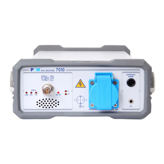
1.8 Front Panel Fig. 1-1 7010 Option 00 Front Panel Legend from left to right: - Line Power led - DATA RX-TX Leds which show the serial communication status - RF INPUT N female RF Input connector - RF IN This led indicates if the signal source is from the internal LISN or from the N connector - L1 –... -
Page 14: Rear Panel
1.9 Rear Panel Fig. 1-2 7010 Option 00 Rear Panel Legend from left to right: - Product Label and Serial Number - Mains socket to connect the EUT to the mains through the internal LISN. - Earth ground connector - USER PORT User I/O Port - Fan Cooling Fan controlled by firmware... -
Page 15: Functional Description................................................................. 1.11 Fast And Precise Measurement
The PMM 7010 features a completely new receiver architecture based on 1.10 Functional the most recent DSP and FPGA technology. Description 1.11 Fast and precise This measurement system has been designed for use on any PC with the measurement Windows™ operating system. The PMM 7010 pre-compliance measurement system allows the designer to measure the conducted and radiated interferences of a prototype under test as part of the daily routine. -
Page 16: Emission Measurement
1.12 Emission All electric and electronic devices are potential generators of Electro- Magnetic Interference (EMI). measurements The term EMI thus refers to the electromagnetic energy emitted by a device which propagates itself along cables or through the air and couples with other devices that are present in the surroundings. -
Page 17: Introduction
2.3 Packing and check list enclosed with the Operating Manual. Unpacking Notify any damage to the forwarder personnel as well as to your NARDA Representative. To avoid further damage, do not turn on the instrument when there are signs of shipping damage to any portion of it. -
Page 18: Indication Of The Power Status With Line Led
15.000 meters • Altitude 2.7 Return for Service If the instrument should be returned to NARDA for service, please complete the service questionnaire enclosed with the Operating Manual and attach it to the instrument. To minimize the repair time, be as specific as possible when describing the failure. -
Page 19: Pmm Emission Suite And 7010 Initial Screen Showing The Last Sweep
2.10 Hardware PMM 7010 is delivered from factory ready to use. Remove the receiver from its cardboard shipping box, connect properly the universal power supply and Installation switch ON the Power button. In this way the LINE Led lights up to indicate the receiver is correctly powered. -
Page 20: Using An Artificial Mains Network (Amn Or Lisn)
2.11 Using an Artificial When the PMM 7010 receiver is connected to a LISN to perform conducted interference measurements of the EUT, the RF output of the LISN shall be Mains Network connected to the RF input of the receiver. In order to switch automatically (AMN or LISN) between the lines of the LISN, it shall be connected to the User Port of the receiver thanks to the dedicated cable supplied with the LISN . -
Page 21: The User Port
2.15 The User Port The PMM 7010 features on the rear panel a programmable User Port that can be used to drive external devices or, more generally, to output signals and data. The User Port can easily be programmed and managed; the connector has the following hardware connection: PIN # Signal... - Page 22 2.16 Schwarzbeck Model The following figure shows the HXYZ 9170 Triple Loop Antenna remote cable pin configuration. This cable can be requested to N or arranged HXYZ 9170 Triple arda locally. Loop Antenna Remote Cable configuration for PMM 7010 Fig. 2-2 HXYZ 9170 remote cable configuration for PMM 7010 Installation...
- Page 23 2.17 PMM LISNs The following figure shows the LISN remote cable pin configuration. The cable can be requested to N or arranged locally. Three Phase arda Remote Cable configuration for PMM 7010 (L3-25 excluded) Fig. 2-3 PMM LISN three phase remote cable configuration for PMM 7010 Installation...
- Page 24 2.18 PMM L3-25 The following figure shows the LISN remote cable pin configuration. The cable can be requested to N or arranged locally. Remote Cable arda configuration for PMM 7010 Fig. 2-4 PMM L3-25 remote cable configuration for PMM 7010 Installation...
-
Page 25: Introduction
Below the graph the start and the stop frequency, and loaded limits, if any. When the sweep has been executed, on the bottom of the screen the most important sweep parameters are repeated. Document 7010EN-81007-1.09 - © NARDA 2018 Sweep Mode Operating Instructions... -
Page 26: Analyzer Mode
3.2.2 ANALYZER To enter the ANALYZER Mode it’s enough to depress the Analyzer soft key MODE on the main screen. In this mode the receiver works as a powerful Spectrum Analyzer and the display shows the "spectrum analysis" in the frequency domain. The analysis is done at the selected span frequency. -
Page 27: Detectors
3.3 Detectors PMM 7010 has been designed to allow the use of many kinds of detectors. CISPR Standard has introduced the application of two detectors that are derived from the Root Mean Squared and from the Average ones. 3.3.1 RMS-AVG The RMS-Average detector is a payment special function implemented in Definition the PMM 7010 receiver. -
Page 28: C-Avg Definition
3.3.3 C-AVG CISPR 16-1-1 defines the Average detector as designed to indicate the weighted average value of the maximum value of the envelope of the signal Definition passed through the pre-detector stages: up to 1000 MHz, is defined as the response of the measuring receiver to pulses of repetition rate n Hz and impulse area of 1,4/n mVs emf at 50Ω... -
Page 29: Rbw Filters
With the Peak, RMS and AVG detectors the smallest settable measurement time depends on the RBW. If several detectors are used contemporarily the Hold Time should be set to meet the requirement of the slowest one, so that the results of the measurement are correct for all them. -
Page 30: Hold Time
3.5 Hold Time The Hold Time (expressed in milliseconds) represents the time the receiver uses to “take a snapshot” of the incoming signal and to measure it with the chosen detector. When selecting a detector, the default hold time value is automatically loaded, but in some cases this time is not appropriate, e.g. -
Page 31: Measuring The Emi Voltage
Some types of Coupling Networks are: AMN (Artificial Mains Network), also known as "LISN" (Line Impedance Stabilization Network), Current Probe and Voltage Probe. Again, Fig. 7-1 also shows the AMN principle. The PMM 7010 is already equipped with a built-in LISN. Document 7010EN-81007-1.09 - © NARDA 2018 Applications... -
Page 32: Amn Principle: A) Δ-Type Or T-Type Lisn ; B) V-Type Lisn
V-LISN test mains 250 μ H 50 μ H 0.25 μ F receiver mains 50 Ω 2 μ F 8 μ F lowpass 5 Ω highpass filter filter V-LISN (only one line is shown) test receiver RF load to interference asym asym unsym... -
Page 33: Current Probe
4.1.2.2 Current Probe Current Probes may be Clamp-on Probes or Fixed-ring Probes. Current Probes are used to measure differential or common mode RFI currents. In some cases it may be important to make a distinction between the two kinds of current flowing in a system. RFI current measurements with Current Probes may be required, for example, when measuring EMI from shielded lines or from complex wiring systems, when finding interference sources among other sources in a... -
Page 34: Test Setup
4.1.3 Test Setup Fig. 7-2. shows an example of test setup for RFI voltage measurement. The DUT is placed 0,4 m from an horizontal or vertical earthed conducting surface of at least 2 m x 2 m in size. A table top DUT is placed 0,8 m from the LISN and at least 0,8 m from any other earthed conducting surface. - Page 35 4.1.5 Remarks and Hints To avoid errors caused by ambient interference, measurements should be carried out inside a properly shielded room. Different sites, like basements for Measuring or other rooms with low ambient interferences, are often sufficient for a preliminary evaluation. Conducted measurements strictly...
- Page 36 This page has been left blank intentionally Applications...
-
Page 37: Introduction
7010 Software Utility stored on Software Media Installation and included in PMM 7010 Receiver package; anyway it’s always possible to check for newer releases and download them from official NARDA Italy Web Site Support page. The User must have administrator privileges to install the 7010SeriesUp software in Windows 7;... - Page 38 Click on “7010SeriesUp” (7010SeriesUp.exe) once for running the update program, so getting the following window: Two firmware components can be updated by this application: Firmware, which is the receiver internal program, and FPGA, to update the internal programmable logic. The 7010FW.ldr file required for Firmware updating and the main7010.bin file for FPGA are automatically stored in the same directory of the 7010SeriesUp.exe, otherwise just copy them there before performing the upgrade.
-
Page 39: To Transfer Data
The program will display the following window: 5.5 To transfer data To start the process simply switch PMM 7010 on, select Update Firmware or Update FPGA button, and wait until the automatic transfer is completed. During the firmware storing procedure, a blue bar will progress from left to right in the window of the PC, showing percentage of downloading time by time until 100%. - Page 40 PMM 7010 receiver either switched On or Off. To obtain up-to-date Firmware or PC Utility for PMM 7010, the user can contact his NARDA distributor or download it directly from Support area of EMC Product Range on the following Web Site: www.narda-sts.it.
-
Page 41: Wrdongle Utility
The WrDongle utility allows to enable the function ordered such Options utility using the 40 Digit Activation Code received from NARDA Italy. Turn on the PMM 7010 and connect it to a free USB or RS232 port of the Browse for All Programs from the Start Menu and reach the “WrDongle”... - Page 42 The program will display the following window: Copy and paste the 40 Digit Activation Code to the “Dongle Code” input field and press the button below related to the specific Option: In case of failure, an error message is showed instead. Always cycle OFF and ON the receiver to properly initialize the function.
-
Page 43: Introduction
• PMM 9010/30P EMI Receiver 10 Hz ÷ 3 GHz; • PMM 9010/60P EMI Receiver 10 Hz ÷ 6 GHz; • PMM 7010 EMI Receiver 9 kHz ÷ 3 GHz Document 7010EN-81007-1.09 - © NARDA 2018 PMM 9010-RMA Rack Mount Adapter... -
Page 44: Pmm 9010-Rma Main Specifications
Table 6-1 lists the PMM 9010-RMA specifications. 6.4 PMM 9010-RMA Main Specifications TABLE 6-1 Technical Specifications 0° to 40°C Environment temperature Rack unit Dimensions 483 x 410 x 132,5 mm (WxDxH) 5,5 Kg (without instruments) Weight 6.5 PMM 9010-RMA Front view Fig. -
Page 45: Pmm 9010-Rma Inside View
6.6 PMM 9010-RMA Inside view Fig. 6-2 Inside view Legend:: 1 – Round holes of service 2 – Rectangular holes used to put 9010, 9010/03P/30P/60P or 7010 Instrument; 3 – 9010, 9010/03P/30P/60P or 7010 straps; 4 – Rectangular holes for future implementation; 5 –... -
Page 46: Rack Requirements
The rack must be of the following type: 6.7 Rack Requirements - Standard 19 inch (483 mm) with mounting rails that conform to English universal hole spacing per section 1 of ANSI/EIA-310-D-1992. - The minimum vertical rack space per chassis must be 3U (rack units), equal to 3 inches (132,5 cm). - Page 47 6.10 Installation When installing the chassis, follow these guidelines: guidelines - Plan your site configuration and prepare the site before installing the chassis. - Ensure that there is adequate space around the rack to allow for servicing the chassis and for airflow. - If the rack has wheels, ensure that the brakes are engaged or that the rack is otherwise stabilized - For a round hole (tapped) rack, use...
- Page 48 6.11 Installing the This section describes how to install the PMM 9010-RMA Rack Mount Adapter: PMM 9010-RMA - Insert the cage nuts behind the vertical rails with respect to the Rack Unit Boundary and the distance show below: ou can use a rack-insertion tool or a flat-blade screwdriver to install the cage nuts.
-
Page 49: Pmm 9010-Rma With 9010 Instrument
6.12 Use of the The following procedure is indifferently referred to the 9010, PMM 9010-RMA 9010/03P/30P/60P or 7010. with PMM 9010 This section provides the information needed to install your 9010 or 7010 Instrument on the PMM 9010-RMA Rack Mount Adapter. - Remove the frontal panel from the Rack unscrewing the milled knob without loosing it completely. - Page 50 This page has been left blank intentionally PMM 9010-RMA Rack Mount Adapter...
-
Page 51: Introduction
7.4 Format Commands are made of ASCII string delimited character “#” (0x23) and the character “*”(0x2A) Replies are terminated with <CR><LF> (\r\n) All the following examples are indifferently referred to the PMM 7010. Document 7010EN-81007-1.09 - © NARDA 2018 Remote control... -
Page 52: List Of Commands
7.5 List of commands Query COMMANDs Syntax Function Tells whether the apparatus is a PMM 7010 and in which mode ?3PR* Requests the Attenuator status for Analyzer mode. ?AAT* ?ACE* Requests the Center frequency for analyzer mode ?ADT* Requests the detector used for Analyzer mode Requests the Hold Time for Analyzer mode. - Page 53 Setting COMMANDs Syntax Function Aborts a sweep currently in progress ASBK Suspends a sweep currently in progress ASPA ASRE Resumes a sweep previously paused S3PRC Sets the PMM 7010 to conducted mode Sets the PMM 7010 to radiated mode S3PRR Sets Attenuator for Analyzer Mode SAAT a SADT b...
-
Page 54: Query Commands
7.6 PMM 7010 Following are Commands to control and set various operating modes of PMM 7010, that can be distinguished in two main groups: COMMANDs • Query Commands • Setting Commands 7.6.1 Query Description COMMANDs ?3PR This query command #?3PR * sends back a string expressing whether the apparatus is a PMM 7010 and in which mode. - Page 55 ?CFA This query command #?CFA* sends back a string in the format CFA=n,(LABEL) where n is the ID of the conversion factor as shown in 7010 menu and LABEL is its temporary name as it was last labelled. If No conversion factor is active the reply CFA= NONE Example of reply: CFA=1,(PROBE) means that conversion factor 1 is active and it was last named as PROBE...
- Page 56 ?LSN This query command #?LSN* sends back a string showing which Band B input is selected in the format: LSN=n Where n can be: • 0 Input on N connector • 1 Input on 7010 internal LISN L1 •...
- Page 57 ?TAT This query command #?TAT * sends back a string expressing MinAtt value. The reply is a string representing the minimum reachable value of attenuator in dB Example of reply: TAT=10 which means that MinAtt is 10dB ?TMP This query command #?TMP* sends back a string showing the temperature expressed in Celsius (°C) .
-
Page 58: Setting Commands
7.6.2 SETTING Behaviour Commands ASBK This command aborts a sweep currently in progress previously started by command SSFD. The reply is either: • SBK=OK which means the sweep has been stopped and all setting commands are available again. • SBK=SERR which informs that the sweep was not in need to be stopped This command suspends a sweep currently in progress previously started by ASPA command SSFD. -
Page 59: Analyzer Reply
SADT b This setting command sets the detector for Analyzer Mode. The argument (b) should be a index representing the detetector as follows: 1 Peak 2 Avg 3 Rms The reply is SADT =OK which acknowledges the command has been granted or SADT =SERR if the command has been ignored. - Page 60 SCFE n, name This setting command is used for saving the conversion factor (made by SCFW). The command is made of the string: • FCE (the command itself), • n is the index and should be 0 (other index are ignored) •...
- Page 61 SDMV v This setting command sets the volume of demodulator. The string (v) should be in the range of 0 to 100. The reply is DMV =OK which acknowledges the command has been granted or DMV =SERR if the command has been ignored. Example: #SDMV 50* Sets the volume of demodulator to half of the audio power.
- Page 62 This setting command sets the Margin to be used with Smart Detector function. The SLIM n argument (n) in the range of -20 to 20. The reply is LIM =OK which acknowledges the command has been granted or LIM =SERR if the command has been ignored. Example: #SLIM 2* Sets the threshold of smart detector to 2 dB below the limit.
- Page 63 SMAN This setting command puts the 7010 in manual mode. The reply is always MAN=OK which acknowledges the command has been granted. The 7010 goes to manual mode. Example: #SMAN * This setting command puts the 7010 in manual mode and sets the default value to SMANP the following settings: •...
- Page 64 Arguments are as follows: SSFD FreqStart; • FreqStart = Sweep Start Frequency expressed in Hz FreqStop; • FreqStop = Sweep Stop Frequency expressed in Hz FreqStep; • FreqStep = Sweep Step Frequency expressed in Hz Detector; If FreqStep > 0 then a standard sweep, tuned step by step, is HoldTime;...
- Page 65 (Continued) • Preamp. This Parameter switches the Preamplifier On or Off according to its content as follows. SSFD FreqStart; On. It turns ON the preamplifiaer. FreqStop; Off. It turns Off the preamplifiaer. FreqStep; • Preselector. This Parameter switches the Preselector On or Off according Detector;...
- Page 66 (Continued) Once the sweep is started, the 7010 sends the value of each detector chosen in the command. Each detector is made of a Little Endian 16 bit integer which represents SSFD FreqStart; the value of that particularly tuned frequency. The value is expressed in hundredth FreqStop;...
- Page 67 SSFW n,freq This setting command is used for creating a Frequency-Scan-Tab frequency by frequency. It is made of two fields as follows: • n Is the index of frequency being written and it should range from 0 to 99 • freq Is the frequency, expressed in Hz (exponential notation allowed), being written The procedure to make and use a Frequency-Scan-Tab on PMM7010 is the...
- Page 68 7.6.3 Analyzer The PMM 7010 replies to the command “SAGO” sending back an array of bytes Reply which contains all the information needed to draw a sweep. Typically, the user should first send the PMM 7010 all the setting commands to insure the receiver is correctly set on the wanted parameters and then read the reply.
- Page 69 ********** End of Header ********** (continued) From here all figures represent the level referred to the tuned frequency And are expressed in hundredth of dBm Level Fstart Little Endian 16 bit integer representing the level referred to start frequency. Level Fstart Little Endian 16 bit integer representing the level referred to start frequency +Fstep plus step frequency...
- Page 70 The PMM 7010, in order to optimize memory, stores measures (sweeps) in dynamic 7.6.4 Sweep mode. This means that a single sweep does not have a fixed size but it varies Structure depending on the sweep itself. Moreover, in order to have a sweep made of different steps (as for example band A and band B), often sweeps are split into two single sweeps.
- Page 71 Sweeps header Sweep #n ID Byte Mnemonic Meaning 513+(n-1)*32 Start Little Endian 32 bit Float figure representing the start frequency of sub- 514+(n-1)*32 Frequency sweep #1 Sub1 515+(n-1)*32 516+(n-1)*32 517+(n-1)*32 Stop Little Endian 32 bit Float figure representing the Stop frequency of sub- Frequency sweep #1 518+(n-1)*32...
- Page 72 Then, the arrays containing the level related to the tuned frequencies can be interpreted using the data OffRec and LenRec (respectively OffRec1, LenRec1 for sweep 1 and OffRec2, LenRec2 for sweep 2) as follows: Level Array From here all figures represent the level referred to the tuned frequency And are expressed in hundredth of dBm OffRecn+1 Level Fstart...
- Page 73 7.6.5 Procedure Send the command #?FSF n * . Wait for the size of array to read a Wait for the first 1024 bytes in order to get both main and sweeps header measure Read the relevant data concerning Start, Stop of full sweep as well as single stored by sub-sweeps if they are more than one.
- Page 74 7.7 Sweep Mode This is the sequence used by the PMM Emission Suite when a scantable is run, in the “conducted” range (Band B from 0.15 to 30 MHz). commands sequence example Example Command sent Reply received Description #?IDN* Queries information about model, release and date of the firmware IDN=7010/03-FW - 1.09 11/06/14 It is a 7010/03 with its FW It is used to check congruencies, frequency limits, and all the related...
- Page 75 Moreover, we are continuously improving our quality, but we know this is a never ending process. We would be glad if our present efforts are pleasing you. Should one of your pieces of NARDA equipment need servicing you can help us serve you more effectively filling out this card and enclosing it with the product.
- Page 76 Suggerimenti / Commenti / Note: Suggestions / Comments / Note:...