Advertisement
Manual
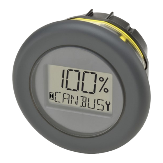
Model 3140
CAN Instrumentation
Read Instructions Carefully!
Specifications are subject to change without notice.
© 2017 Curtis Instruments, Inc. ® Curtis is a registered trademark of Curtis Instruments, Inc.
© The design and appearance of the products depicted herein are the copyright of Curtis Instruments, Inc.
Curtis Instruments, Inc.
200 Kisco Avenue
Mt. Kisco, NY 10549
www.curtisinstruments.com
53091 Rev C 11/17
Advertisement

Summary of Contents for Curtis 3140
- Page 1 Specifications are subject to change without notice. © 2017 Curtis Instruments, Inc. ® Curtis is a registered trademark of Curtis Instruments, Inc. © The design and appearance of the products depicted herein are the copyright of Curtis Instruments, Inc. 53091 Rev C 11/17...
-
Page 2: Table Of Contents
Table 2: CAN Object Dictionary ......................8 Table 3: ASCII Character Table ......................13 Table 4: Specifications ........................14 FIGURES: Figure 1: Curtis Model 3140 ....................... 1 Figure 2: 3140 Dimensions ........................ 2 pg. ii Curtis 3140 Manual – Nov. 2016... -
Page 3: 1-Introduction
• Industry standard 52mm panel cutout allows the use of exising panel/tool designs thereby lowering development cost. • Battery State-of-Charge (BSOC) can be calculated in the 3140 or sent to the 3140 by the Model F2A (or equivalent CANopen-based motor controller). -
Page 4: 2: Installation And Wiring
Curtis 3140 Manual – Nov. 2017 2 — INSTALLATION AND WIRING MOUNTING THE INSTRUMENT The outline and dimensions for Model 3140 are shown in Figure 2. Figure 2 3140 product dimensions in mm. 29.0 MIN 35.0 VIEWING Ø 60.0 AREA 19.4 MIN... -
Page 5: 3: Canopen Communications
NODE ADDRESSES The node address of the Model 3140 can be 1 to 127 and is used by CANopen to route messages to the Model 3140 and to denote messages from the Model 3140. The node address is part of the COB-ID and therefore also plays a part in message priority and bus arbitration. - Page 6 NMT (Network Management Transmission) messages are the highest priority message available. The NMT message puts the Model 3140 into one of the four defined states. These messages have 1 byte of data sent by the master; the slave does not respond with any data to an NMT. The Model 3140 state value is transmitted with each heartbeat message.
- Page 7 The heartbeat message is a very low priority message, periodically sent by each slave device on the bus. The heartbeat message has a single byte of data and requires no response. Once the Model 3140 is in the Pre- Operational state, the next heartbeat will be issued and will continue until communication is stopped.
- Page 8 Curtis 3140 Manual – Nov. 2017 POWER-UP SEQUENCE Upon power-up or transition from Pre-operational to Operational state, the 3140 will go through a three- second diagnostic sequence. The LCD will be blank for the first second, then turn on all segments for one second, then blank for one second.
- Page 9 CAN object 0x3010, sub-index 0x00 Byte 6 Hourmeter Value Byte 2 CAN object 0x3010, sub-index 0x00 Byte 7 Hourmeter Value Byte 3 CAN object 0x3010, sub-index 0x00 PDO2_TX No PDO2_TX message is transmitted by the 3140. 3 — CANopen COMMUNICATIONS pg. 7...
-
Page 10: 4: Device Parameter Objects
Curtis 3140 Manual – Nov. 2017 4 — DEVICE PARAMETER OBJECTS DICTIONARY OBJECTS The following Table identifies the variables that should be externally accessible for the 3140. Table 2: CAN Object Dictionary CAN Index Sub-Index Name Length Read/ Write Default Value... - Page 11 Curtis 3140 Manual – Nov. 2017 Table 2: CAN Object Dictionary continued CAN Index Sub-Index Name Length Read/ Write Default Value (Bytes) 0x1600 0x02 can_pdo_RX_1_map_2 0x30010108 0x1600 0x03 can_pdo_RX_1_map_3 0x30010208 0x1600 0x04 can_pdo_RX_1_map_4 0x30010308 0x1601 0x00 can_pdo_RX_2_length 0x06 0x1601 0x01...
- Page 12 Curtis 3140 Manual – Nov. 2017 Table 2: CAN Object Dictionary continued CAN Index Sub-Index Name Length Read/ Write Default Value (Bytes) 0x3005 0x00 Backlight percent (0 – 100%) 0x3010 0x00 Hourmeter value (internal) 0x3010 0x01 Hourmeter enable (0 =...
- Page 13 Curtis 3140 Manual – Nov. 2017 Description of variables not defined in CiA 301 Large_Display_Length: This is the length of the large text display in characters. This should be hard-coded to a value of 3. Large_Text_Char_1: This is the ASCII code for the first (leftmost) character to be placed on the large 3-character display, if selected in Byte 1 of the Command_Word.
- Page 14 Curtis 3140 Manual – Nov. 2017 BDI_CTR_empty: The “empty” parameter for the charge-tracking-reset curve, in mV per cell. BDI_OCR: The open-circuit reset value, in mV per cell. BDI_integration_time: The integration time, in minutes. B+_nominal: The nominal B+ system voltage, in volts, e.g. 24, 36, 48.
- Page 15 Curtis 3140 Manual – Nov. 2017 Table 3 ASCII Character Table 4 — DEVICE PARAMETER OBJECTS pg. 13...
-
Page 16: 5: Specifications
Curtis 3140 Manual – Nov. 2017 5 — SPECIFICATIONS The specifications for the Curtis Model 3140 are presented in Table 4. Table 4 Specifications ENVIRONMENTAL –10°C to +85°C (with optional LCD heater: –40°C to +85°C). Operating Temperature: –40°C to +85°C. - Page 17 Curtis 3140 Manual – Nov. 2017 Table 4 Specifications continued EMC SPECIFICATIONS Designed to meet UN ECE/324 Addendum 9 Regulation 10 Revision 4 (6 March Emissions (Broadband & Narrowband): 2012) for an Electrical/electronic sub-assembly (ESA). Immunity: Designed to meet IEC 61000-4-2: Test level IV (8 kV contact discharge or 15 ESD: kV air discharge) according to ISO 10605:2001, Table B.1.