Advertisement
Advertisement
Table of Contents

Related Manuals for Planar Clarity Matrix

Summary of Contents for Planar Clarity Matrix
- Page 1 Clarity Matrix Fiber Video Extension User Guide...
- Page 2 Planar employees. When you purchase a Planar product, you get more than a display, you get the service and support you need to maximize your investment. To find the latest warranty and service information regarding your Planar product, please visit http://www.planar.com/support...
-
Page 3: Manual Scope
Fiber Video Extension option provides a more secure and longer distance option for extending the video signal from the off-board electronics to the Clarity Matrix LCD modules. Features of the Fiber Video Extension option include: • Utilizes fiber optic cable to extend the Matrix G2 video signal •... -
Page 4: System Architecture
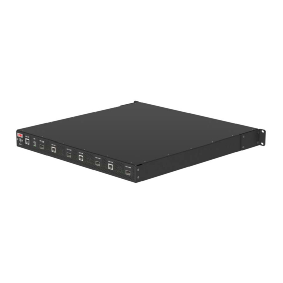
Power Supply distance, Quad Controllers may need to be separated from the Power Supply module and powered from an optional DC Power Brick. See the Clarity Matrix LCD Video Wall System with G2 Architecture Installation Guide for information. - Page 5 Fiber Video Extension Module – Rear View Fiber module USB 2.0 power switch (Type-B connector) SFP fiber transceiver connection output to the panel Input from the Quad Controller DC Power (4-pin mini-DIN) for Fiber module © 2015 Planar Clarity Matrix Fiber Video Extension User Guide...
-
Page 6: Installing The Fiber Video Extension
Includes AC cable (2.5 m). USB cable (3 m) Connects a PC to the Fiber Video Extension module for USB devices located at the panel, such as a touch sensor. © 2015 Planar Clarity Matrix Fiber Video Extension User Guide... -
Page 7: Optional Accessories
1.25 and 2.50 mm VFL ferrule adapters and all required fiber preparation, cleaning tools and materials. 175-1068-00 Cable Assy, PWR, AUX, TOUCH. Used to connect the optional touch sensor to the LCD panel for DC power. © 2015 Planar Clarity Matrix Fiber Video Extension User Guide... -
Page 8: Connecting Cables
Quad Controller module and the LCDs. It does not cover how to install the LCDs, Quad Controller modules, and power supply. For detailed installation instructions, refer to the Clarity Matrix LCD Video Wall System with G2 Architecture Installation Guide. - Page 9 Plug the other end of the fiber optic cable into the transceiver. Connect the DC power brick to the Fiber Video Extension module and plug the AC power cord into the power source. © 2015 Planar Clarity Matrix Fiber Video Extension User Guide...
-
Page 10: Connecting The Usb Option
USB extension when using Clarity® Matrix™ MultiTouch interactive LCD video wall displays and other USB devices at the video wall. The LCD modules can also provide power for Clarity Matrix MultiTouch, eliminating the need for separate AC power connection at the video wall. - Page 11 Dimensions Fiber Video Extension Module Transceiver © 2015 Planar Clarity Matrix Fiber Video Extension User Guide...
-
Page 12: Fiber Video Extension Module Specification
–4° F Fan Noise 45dB Altitude (barometric pressure) 2000m Above sea level, or equivalent barometric pressure. De-rate temperature 10° for every 1km above 1000m. Humidity operating 80% R.H. 20% R.H. non-condensing © 2015 Planar Clarity Matrix Fiber Video Extension User Guide...