Advertisement
Quick Links
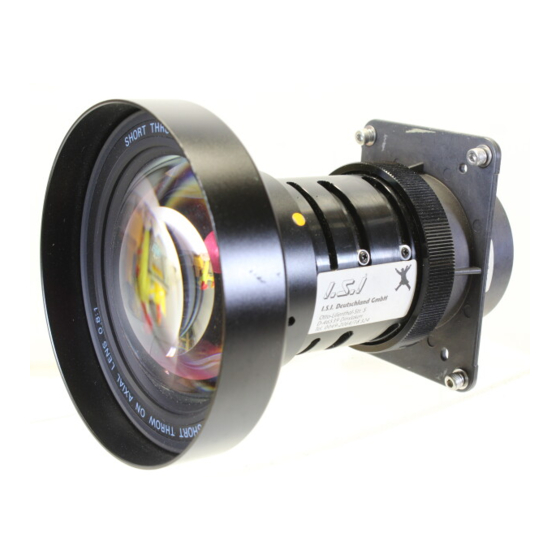
LCD PROJECTOR LENS
MODEL LNS-W32
LENS REPLACEMENT PROCEDURE
NOTE; Lens installation is different in cabinet design and lens attachment method
(Type A, B and C). Before installation the lens, check cabinet design and
proper installation should be made.
NOTES ON LENS REPLACEMENT
The ZOOM, FOCUS and LENS SHIFT adjustment on the Top Control or the
Remote Control cannot be operated with this Lens.
Lens replacement should be performed by the qualified service personnel.
It should be followed by this procedure precisely.
Before attempt to replace the lens, confirm the model number (both the LCD
projector and the lens) and use the proper lens.
The lens cover is on the lens for protection. Be sure to remove the lens cover
before installation.
When installing or removing the lens, be careful not to stain, scratch or
damage the lens.
Following parts are contained in the packing.
● LENS
● LIGHT-BLOCK SHEET BASE
● DRIVER (3 mm, Green)
● DRIVER (4 mm, Yellow)
● LIGHT-BLOCK SHEET
● SCREW
Following checks and confirmations should be taken for safety.
Check the following things by the time of the cabinet assembly after the lens
replacement.
1. Check the lens is securely fixed.
2. Check no parts is missing, or no mounting part is loose.
Some parts are not used for installation or replacement. Keep these parts and
drivers included in the lens for later use.
PARTS LIST
1 piece
1 piece (Part No. 610 310 8001)
1 piece (Part No. 610 287 7328)
1 piece (Part No. 610 275 6029)
1 piece Type PC1 (Part No. 610 310 7967)
1 piece Type PD1 (Part No. 610 294 3047)
2 pieces (Spare parts)
1AA6P1P3217A- (ICZAA-A)
Advertisement

Related Manuals for Sanyo LNS-W32


Summary of Contents for Sanyo LNS-W32
-
Page 1: Parts List
LCD PROJECTOR LENS MODEL LNS-W32 LENS REPLACEMENT PROCEDURE NOTE; Lens installation is different in cabinet design and lens attachment method (Type A, B and C). Before installation the lens, check cabinet design and proper installation should be made. NOTES ON LENS REPLACEMENT The ZOOM, FOCUS and LENS SHIFT adjustment on the Top Control or the Remote Control cannot be operated with this Lens. - Page 2 LENS REPLACEMENT PROCEDURE (FOR "A" TYPE) NOTE; When installation of this lens to the "A" type, needs an additional Front Panel. Contact to our sales dealer for ordering. Perform the steps First set the lens at the center position with lens shift adjustment.
- Page 3 REMOVE THE LENS (See Figure-5 and 6) Disconnect the Lens Shift connector "K16L" from the circuit board on cabinet left side. Disconnect the Zoom and Focus connector "K16J" from the circuit board. Remove the lens motor lead from lead holder. Remove screws-C (4 screws) which fastens the lens and remove the lens.
-
Page 4: Focus Adjustment
MOUNT THE LENS (See Figure-5 and 6) Remove protective caps (front and back) on the lens. Mount the lens on lens mounting bracket with 4 screws. Use the driver (4 mm, Yellow) included with the lens to fasten the screws. CONFIRM THE FOCUS Project picture on screen and confirm the focus. - Page 5 LENS REPLACEMENT PROCEDURE (FOR "B" TYPE) Perform the steps First set the lens at the fully lower position with lens shift adjustment. REMOVE THE LENS COVER AND FRONT CABINET Turn the lens cover to counter-clockwise and pull it toward front and remove the Lens Cover.
- Page 6 REMOVE THE LENS (See Figure-3 and 4) Remove the lens motor connector from terminal. Loosen the screws-B (2 screws) which fastens the lens. {Use the driver (4 mm, Yellow) included with the lens to loosen the screws.} Slide the lens lock latches to "UNLOCK" position and remove the lens.
- Page 7 MOUNT THE LIGHT-BLOCK SHEET AND LIGHT-BLOCK SHEET BASE (See Figure-6) Mount the light-block sheet on the lens. (In the same position as the removed sheet has been placed). Use the sheet included with the lens. Make sure the mark (TOP and BACK) on Light-Block Sheet and set them properly.
- Page 8 LENS REPLACEMENT PROCEDURE (FOR "C" TYPE) Perform the steps First set the lens at the fully lower position with lens shift adjustment. REMOVE THE LENS COVER AND FRONT CABINET Turn the lens cover to counter-clockwise and pull it toward front and remove the Lens Cover. Remove 2 Screws-A.
-
Page 9: Mount The Lens
MOUNT THE LENS Remove protective caps (front and back) on the optional lens. Mount the lens on the lens attachment with 4 Screws. Connect the lens motor lead connector to the socket on the lens attachment. Grasp the Lens Lock Lever and turn it fully upward. Install the Lens into the projector. Turn the Lens Lock Lever fully downward until lever is Locked (clicked position) properly. - Page 10 MOUNT THE LIGHT-BLOCK SHEET AND LIGHT-BLOCK SHEET BASE Mount the light-block sheet on the lens. (In the same position as the removed sheet has been placed). Use the sheet included with the lens. Make sure the mark (TOP and BACK) on Light-Block Sheet and set them properly.