NETGEAR ReadyDATA 5200 Hardware Manual
Hide thumbs
Also See for ReadyDATA 5200:
- Installation manual (15 pages) ,
- Installation manual (15 pages) ,
- Software manual (203 pages)

Related Manuals for NETGEAR ReadyDATA 5200


Summary of Contents for NETGEAR ReadyDATA 5200
- Page 1 ReadyDATA 5200 H ardwa re M a nual 350 East Plumeria Drive San Jose, CA 95134 December 2012 202-11024-03...
- Page 2 Trademarks NETGEAR, the NETGEAR logo, and Connect with Innovation are trademarks and/or registered trademarks of NETGEAR, Inc. and/or its subsidiaries in the United States and/or other countries. Information is subject to change without notice. © 2012 All rights reserved.
-
Page 3: Table Of Contents
Table of Contents Chapter 1 Getting Started Front Panel ..........5 Rear Panel . -
Page 4: Chapter 1 Getting Started
Factory Settings • Technical Specifications This manual assumes that your ReadyDATA 5200 has been installed in a rack according to the instructions in the NETGEAR ReadyDATA 5200 Installation Guide. For detailed information about configuring, managing, and using your ReadyDATA 5200 storage system, see the ReadyDATA OS Software Manual, which is available on the Resource CD that came with your storage system and at http://support.netgear.com. -
Page 5: Front Panel
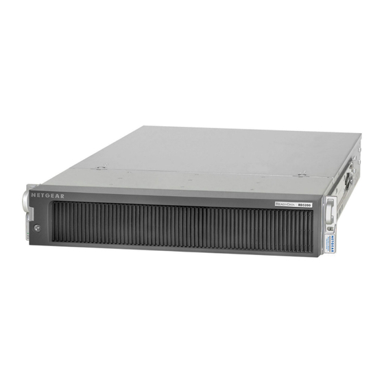
NETGEAR ReadyDATA 5200 Front Panel The following figure shows the front panel of the ReadyDATA 5200 with the optional front bezel removed. Figure 1. ReadyDATA 5200 front panel 1. Drive bays with disk status LEDs 2. Control panel The following figure shows the control panel in more detail. - Page 6 Replace a Disk on page 27. The ReadyDATA 5200 comes with an front bezel that protects the drive bays with a lockable cover. You can operate the ReadyDATA 5200 with or without the front bezel. The following image shows a ReadyDATA 5200 with the front bezel installed.
-
Page 7: Rear Panel
NETGEAR ReadyDATA 5200 Rear Panel The following figure shows the rear panel of the ReadyDATA 5200. Figure 5. ReadyDATA 5200 rear panel 1. Power supplies 2. PS2 keyboard and mouse ports 3. USB ports 4. RS232 console port 5. VGA monitor port... - Page 8 NETGEAR ReadyDATA 5200 Table 1. Status indicators (continued) Indicator Description Information LED The LED has these states: • On. Overheating or fan failure • Off. Normal operation Disk LEDs on disk tray with The top LED indicates disk activity as follows: SAS drives or SSD with •...
-
Page 9: Boot Menu
NETGEAR ReadyDATA 5200 Boot Menu Use the boot menu to restart or troubleshoot your ReadyDATA 5200. It has the following boot modes: • Normal. Initiates a normal boot process, just like booting using the Power button. • Factory default. Initiates a reboot process that resets the system to factory settings and clears all data. - Page 10 NETGEAR ReadyDATA 5200 Press and release the Reset button to scroll through the boot menu options. Watch the blink pattern of the power diagnostic LED and the information LED. The following table shows the how the system displays the current option using the power diagnostic LED and information LED.
-
Page 11: Factory Settings
NETGEAR ReadyDATA 5200 Factory Settings The following table lists factory settings for the ReadyDATA 5200. Table 2. Factory settings Feature Default Login User login URL when the ReadyDATA https://169.254.x.x 5200 is not connected to a DHCP server The last two octets are randomly generated based on the system’s MAC address. -
Page 12: Technical Specifications
NETGEAR ReadyDATA 5200 Technical Specifications The following table lists the technical specifications for the ReadyDATA 5200. Table 3. ReadyDATA 5200 technical specifications Feature Specification Electrical Power supplies (PSU) Two 700W server-rated AC power supplies Input 100–240V AC, 50/60Hz Power consumption... -
Page 13: Chapter 2 Expansion Disk Arrays
The disk expansion arrays do not work independently; instead, they must be connected to a ReadyDATA 5200. For information about how to connect an expansion disk array to a ReadyDATA 5200, see the NETGEAR ReadyDATA 5200 Installation Guide that came with the EDA2000, EDA4000, and ReadyDATA 5200. -
Page 14: Front Panel
NETGEAR ReadyDATA 5200 Front Panel The following figure shows the front panel of the EDA2000 (2U expansion disk array), top, and EDA4000 (4U expansion disk array), bottom, with the optional front bezel removed. Figure 6. EDA2000 front panel and EDA4000 front panel 1. - Page 15 NETGEAR ReadyDATA 5200 The following figure shows the control panels in more detail. Figure 7. EDA2000 and EDA4000 control panels 1. Power button 2. Reset button 3. Power LED 4. Ethernet LED 5. Power diagnostic LED 6. Disk activity LED...
-
Page 16: Rear Panel
NETGEAR ReadyDATA 5200 For more information about adding and replacing disk drives, see Add a Disk on page 23 and Replace a Disk on page 27. The EDA 2000 and EDA 4000 come with an front bezel that protects the drive bays with a lockable cover. -
Page 17: Status Information
NETGEAR ReadyDATA 5200 Status Information The status indicators on the EDA2000 and EDA4000 are the same as on the ReadyDATA 5200. For more information, see Table 1, Status indicators on page 7. Technical Specifications The following table lists the technical specifications for the EDA2000. - Page 18 NETGEAR ReadyDATA 5200 The following table lists the technical specifications for the EDA4000. Table 5. EDA4000 technical specifications Feature Specification Electrical Power supplies (PSU) Two 700W server-rated AC power supplies Input 100–240V AC, 50/60Hz Power consumption 170W typical with six 1-TB disks...
-
Page 19: Chapter 3 Maintenance
Maintenance This chapter describes how to perform maintenance activities like adding disks and replacing disks and system components. It includes the following topics: • Front Bezel • Disks • System Components... -
Page 20: Front Bezel
NETGEAR ReadyDATA 5200 Front Bezel The ReadyDATA 5200, EDA2000, and EDA4000 come with a front bezel that protects the drive bays with a lockable cover. You can operate these systems with or without the bezel. To install the front bezel: ... - Page 21 NETGEAR ReadyDATA 5200 To remove the front bezel: If the bezel is locked, unlock it. Push the release latch on the left side of the bezel. Pull the bezel toward you. Maintenance...
-
Page 22: Disks
NETGEAR or a NETGEAR authorized reseller. Failed Disk Notification When a disk fails in your ReadyDATA 5200, you are notified by email. Email alerts must be set up for notifications to be sent. In addition, Dashboard provides information about the failed disk. -
Page 23: Add A Disk
You can add a hard disk to an empty disk bay. You do not need to shut down your unit before adding a disk. You can use 2.5-inch and 3.5-inch disk drives in a ReadyDATA 5200, EDA2000, or EDA4000. To add a 2.5-inch disk: ... - Page 24 NETGEAR ReadyDATA 5200 Turn the disk over and remove the metal plate from the drive tray. (Optional) Depending on the thickness of the disk drive you are installing, adhere the foam pad to the metal plate in the area bounded by the metal tabs so that the 2.5-inch disk drive will rest on it.
- Page 25 NETGEAR ReadyDATA 5200 Align the screw holes on the disk drive with the screw holes on the metal tabs and install the screws to fasten the disk drive to the metal plate. With the disk tray handle to the right and the hard disk drive to the left, assemble the disk tray and metal plate.
- Page 26 NETGEAR ReadyDATA 5200 To add a 3.5-inch disk: Pull the disk tray release switch. The tray handle pops out. 1. Disk tray handle 2. Disk tray release switch Pull out the disk tray and place a disk in the tray.
-
Page 27: Replace A Disk
NETGEAR ReadyDATA 5200 Replace a Disk If a disk fails, your system provides email alerts and status messages about the need to replace a disk. You do not need to power down your unit when replacing a disk. To replace a 2.5-inch disk: ... - Page 28 NETGEAR ReadyDATA 5200 Remove the screws that hold the disk drive to the metal tabs and remove the old disk drive. Replace the disk drive and reassemble the disk tray. For more information, see Add a Disk on page 23.
- Page 29 NETGEAR ReadyDATA 5200 To replace a 3.5-inch disk: If a disk failed, scan disk LEDs on the disk bays to identify the failed disk. Pull the disk tray release pull switch. The tray handle pops out. 1. Disk tray handle...
-
Page 30: System Components
Secure the locking tab on the unit. Plug the AC power cord back into the unit. System Interior You must access the inside of your ReadyDATA 5200, EDA2000, or EDA4000 to replace a fan or battery. To access the system interior: ... -
Page 31: Fan
NETGEAR ReadyDATA 5200 WARNING: Ensure that the chassis cover is in place when the system is operating to allow proper cooling. Out-of-warranty damage to the system can occur if you do not strictly follow this practice. If a fan fails, the remaining fans increase to full speed, the information LED on the control panel illuminates, and an email alert is sent to the system administrator. -
Page 32: Battery
NETGEAR ReadyDATA 5200 Battery Your system uses a CR2032 battery. Dispose of used batteries according to the manufacturer’s instructions. DANGER: Installing the on-board battery upside down, which reverses its polarities, creates a danger of explosion. Take care to install the battery properly. -
Page 33: Appendix A Warnings And Precautions
Warnings and Precautions This appendix contains safety warnings and precautions for the ReadyDATA 5200 . It includes the following sections: • Safety Warnings • Electrical Safety Precautions • General Safety Precautions • Electrostatic Discharge (ESD) Precautions... -
Page 34: Safety Warnings
NETGEAR ReadyDATA 5200 Safety Warnings The equipment is certified for installation only by trained personnel, according to the installation instructions provided with each unit. The socket outlet shall be installed near the equipment and shall be easily accessible. Observe the on-board battery precautions. Follow the battery replacement instructions in Battery on page 32. -
Page 35: General Safety Precautions
General Safety Precautions Follow these rules to ensure general safety: • Keep the area around the ReadyDATA 5200 clean and free of clutter. • The ReadyDATA 5200 weighs approximately 82 pounds when fully loaded. When lifting the system, two people at either end should lift slowly with their feet spread out to distribute the weight. -
Page 36: Electrostatic Discharge (Esd) Precautions
NETGEAR ReadyDATA 5200 Electrostatic Discharge (ESD) Precautions Electrostatic discharge is generated by two objects with different electrical charges coming into contact with each other. An electrical discharge is created to neutralize this difference, which can damage electronic components and printed circuit boards. The following measures are... -
Page 37: Appendix B Notification Of Compliance
Notification of Compliance Regulatory Compliance Information This section includes user requirements for operating this product in accordance with National laws for usage of radio spectrum and operation of radio devices. Failure of the end-user to comply with the applicable requirements may result in unlawful operation and adverse action against the end-user by the applicable National regulatory authority. - Page 38 NETGEAR ReadyDATA 5200 FCC Declaration Of Conformity We, NETGEAR, Inc., 350 East Plumeria Drive, San Jose, CA 95134, declare under our sole responsibility that the NETGEAR ReadyDATA 5200 complies with Part 15 of FCC Rules. Operation is subject to the following two conditions: •...