Table of Contents
Advertisement
Available languages
Available languages
Operator's Manual
V CUUM PUMP/BR KE BLEED KIT
Model 20930
CAUTION: Before using this
product, read this manual and
follow all its Safety Rules
and Operating Instructions.
Sears, Roebuck and Co., Hoffman Estates, IL 60179, U.S.A.
www.craftsman.com
• Safety
• Operation
• Specifications
• Vacuum Systems
• Diagnostics
• Parts and Accessories
• Español, p. 20
Advertisement
Chapters
Table of Contents

Related Manuals for Craftsman 20930


Summary of Contents for Craftsman 20930
- Page 1 Operator’s Manual V CUUM PUMP/BR KE BLEED KIT Model 20930 CAUTION: Before using this • Safety product, read this manual and • Operation follow all its Safety Rules • Specifications and Operating Instructions. • Vacuum Systems • Diagnostics • Parts and Accessories •...
-
Page 2: Table Of Contents
CR FTSM N ONE YE R FULL W RR NTY If this Craftsman product fails due to a defect in material or workmanship within one year from the date of purchase, RETURN IT TO ANY SEARS STORE OR OTHER CRAFTSMAN OUTLET IN THE UNITED STATES FOR FREE REPLACEMENT. -
Page 3: Service Parts & Accessories
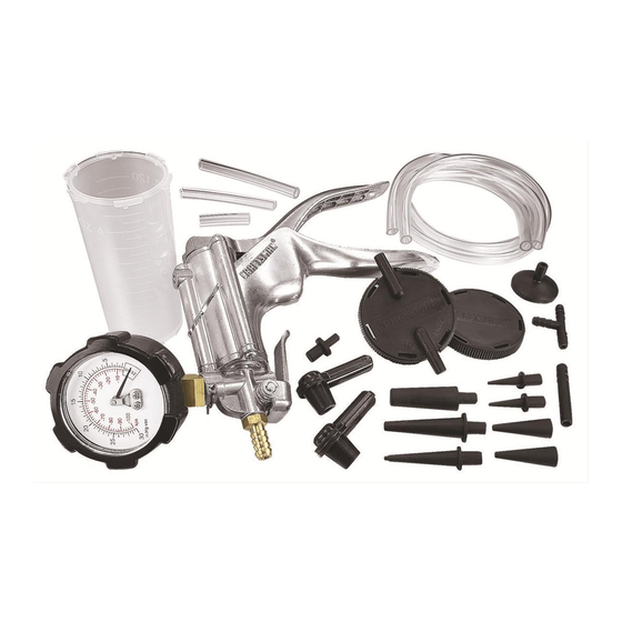
SERVICE PARTS & ACCESSORIES 06172 823373 PUMP SERVICE KITS This Kit 04100 823371 823311 822303 – Adapter Kit 822392 – Suction Cup 822303 – Adapter Kit 822391 – Tubing (2 pieces) 822390 – Reservoir Kit... -
Page 4: The Pump
THE PUMP The vacuum pump is an extremely versatile service SAFETY CAP tool that can be used to test a variety of automotive The small cap on the pressure fitting is pressed on systems and perform a number of useful tasks. with a friction fit. - Page 5 THE PUMP 3) The pump can also be used as a pressure pump by removing the safety cap and connecting to the pressure fitting. When the pump handle is released from the closed position, pressure is created. Additional pressure can be applied by manually pushing in the piston pump rod.
-
Page 6: The Automotive Vacuum System
THE AUTOMOTIVE VACUUM SYSTEM This manual deals with vacuum, how it is used in On the intake stroke, the piston moves down, this various automotive systems and how the vacuum creates a partial vacuum because the volume of the pump can be used to test and diagnose these cylinder is increased. - Page 7 THE AUTOMOTIVE VACUUM SYSTEM VACUUM DISTRIBUTION TROUBLESHOOTING THE VACUUM SYSTEM All modern automobiles have a vacuum distribution Most vacuum problems can be traced to leaks, which system (FIGURE 3), consisting of lines, hoses, occur in hoses, connectors, motor diaphragms or fittings and vacuum devices.
-
Page 8: Diagnosing Mechanical Engine Conditions
THE AUTOMOTIVE VACUUM SYSTEM Venturi Vacuum Carburetor or Throttle Body • Weak or zero at cruise or idle • Strong at wide open throttle EGR Vacuum • Zero at closed throttle Position when “S” and “E” • Still zero when “S” vacuum is on vacuum are “on”... - Page 9 DIAGNOSING MECHANICAL ENGINE CONDITIONS 3) An increase in vacuum over that obtained at idle LEAKING PISTON RING Vacuum at idle will be low but steady at about 12 to indicates an exhaust system that is free of restrictions. 16" Hg. Open the throttle and allow the engine to 4) If the needle drops toward zero as engine RPM pick up speed to about 2000 RPM, and then close is increased, either an exhaust restriction or an...
-
Page 10: Positive Crankcase Ventilation System
POSITIVE CRANKCASE VENTILATION SYSTEM SYSTEM OPERATION 3) Clamp off the vacuum hose to the PCV valve. The Positive Crankcase Ventilation (PCV) system is The engine speed should decrease 100 RPM to used on all modern engines to reduce air pollution indicate the loss of the calibrated air leak into by providing a more complete scavenging of the intake manifold. -
Page 11: Exhaust Gas Recirculation (Egr)
EXHAUST GAS RECIRCULATION (EGR) An Exhaust Gas Recirculation (EGR) system is used Some cars have a Back-Pressure Transducer Valve on most modern engines to reduce Oxides of (BPV) to modulate the operation of the EGR system. Nitrogen (NOx) emissions. During the combustion Some cars have a Venturi Vacuum Amplifier (VVA) process, nitrogen, which makes up 80 percent of to do the same job. - Page 12 EXHAUST GAS RECIRCULATION (EGR) EGR SERVICE PROCEDURES/GENERAL TEST 2) The diaphragm should move to the open position and a decrease in engine RPM should be noted. If EXCEPT GM OR BACKPRESSURE CONTROLLED TYPE not, the valve is defective or the manifold passages If the symptoms of an engine lead you to believe are plugged.
- Page 13 EXHAUST GAS RECIRCULATION (EGR) 2) Check the vacuum connection to the EGR valve Release the diaphragm and record the time it takes for obstructions. for the diaphragm to return to its seated position. 3) Connect the pump between the EGR valve and 6) If it takes less than 20 seconds for the valve to the carburetor or vacuum source.
- Page 14 EXHAUST GAS RECIRCULATION (EGR) EGR VENTURI VACUUM AMPLIFIER BACK-PRESSURE TRANSDUCER VALVE Some engines utilize a Venturi Vacuum Amplifier (BPV) OPERATION that uses the weak vacuum signal from the throat of The Back-pressure Transducer Valve (BPV) controls the carburetor to allow the passage of the stronger the amount of EGR according to the load on the intake manifold vacuum to operate the EGR valve.
-
Page 15: Spark Delay Valves (Sdv)
SPARK DELAY VALVES (SDV) OPERATION To determine if a spark delay valve is operating Spark Delay Valves (SDV) are used to delay vacuum correctly, the following service procedure should to the distributor vacuum advance actuator during be used: hard acceleration, to delay the action of the 1) With the transmission in neutral, set the carburetor Thermactor Air Induction Reaction (AIR) system to the fast-idle position, remove the spark-delay valve... -
Page 16: Electrical/Vacuum Solenoid
ELECTRICAL /VACUUM SOLENOID SERVICE PROCEDURES 1) Disconnect vacuum and electrical connectors from Air Filter the solenoid. Connect the pump to port “B” and attempt to apply vacuum with pump. Vacuum Port “A” should be released through port “A” (FIGURE 12). 2) Using jumper wires, connect negative solenoid terminal to ground and apply 12 volts to the positive terminal. - Page 17 THERMAL-CONTROLLED VACUUM-SWITCHING VALVES 3) If full vacuum flows through the valve when The four-port valve must be tested two times, once heated, it is okay. If there is no vacuum flow or at the top two ports and once at the bottom two there is vacuum flow when the coolant is cold, ports as shown in the accompanying illustration replace the valve.
-
Page 18: Brake Bleeding
BRAKE BLEEDING Many brake systems today feature Anti-Lock accumulator units are fitted with a bleeder valve functions and electronic controls. Many of these which must be bled when the system has lost fluid or systems use a high pressure electric pump to keep is being replaced. - Page 19 BRAKE BLEEDING B) Bleeder fittings on the combination valve, 7) Place wrench on brake bleeding fitting. if equipped. Attach adapter and pump assembly, and pump C) Wheel cylinders and calipers in succession 10 to 15 times. beginning with the wheel closest to the master NOTE: If bubbles coming out of the fitting are very cylinder, and working to the farthest one.
- Page 20 BRAKE BLEEDING MOTORCYCLE BLEEDING PROCEDURE For dual disc front brakes, repeat bleeding process Before bleeding the system, ensure that: as though there are two separate systems. 1) The brake caliper pistons are free to move REAR BRAKE within the calipers. Removing all air from the rear brake line is the 2) The master cylinder piston is free to return to same as for the front.
- Page 21 BRAKE BLEEDING 4) Operate the pump and observe air and fluid BENCH BLEEDNG THE MASTER CYLINDER Whenever a master cylinder has been removed flowing into the reservoir until clear, bubble-free from a vehicle or a new one is being installed, fluid appears.
-
Page 22: Spanish Section
GARANTÍA COMPLETA DE UN AÑO DE CRAFTSMAN Si este producto Craftsman falla debido a un defecto de materiales o fabricación en un plazo de un año desde la fecha de compra, DEVUÉLVALO A CUALQUIER TIENDA SEARS O A OTRO DISTRIBUIDOR CRAFTSMAN EN ESTADOS UNIDOS PARA OBTENER UN REEMPLAZO GRATUITO. -
Page 23: Piezas De Servicio Y Accesorios
PIEZAS DE SERVICIO Y ACCESORIOS 06172 823373 JUEGOS DE SERVICIO DE LA BOMBA Este juego 04100 823371 823311 822303 – Juego de adaptadores 822392 – Ventosa 822303 – Juego de adaptadores 822390 – Juego de depósito 822391 – Tubo (2 pedazos) -
Page 24: Bomba De Vacío
BOMBA DE VACÍO La bomba de vacío es una herramienta de servicio un resorte de muelle de acción giratoria. Al girar versátil que puede usarse para probar diversos sis- despacio el resorte de ruptura de vacío se permitirá temas del automóvil y realizar tareas útiles. Aunque la entrada de aire. - Page 25 BOMBA DE VACÍO mediante un conector en “T”. La bomba puede LUBRICACIÓN funcionar de tres formas distintas como instrumento El lubricante de fábrica es un aceite de silicona que de prueba: 1) Cuando se desee crear un vacío para permite usar la bomba durante mucho tiempo. una prueba, puede apretar simplemente la palanca Si cree necesario lubricar la bomba, utilice un aceite móvil de la bomba con la mano, de forma parecida...
-
Page 26: Sistema De Vacío Del Automóvil
EL SISTEMA DE VACÍO DEL AUTOMÓVIL Este manual trata sobre el vacío, cómo se utiliza POR QUÉ CREAN VACÍO LOS MOTORES en los diversos sistemas del automóvil y cómo El vacío se crea al extraer el aire de cierto espacio, puede utilizar la bomba de vacío para probar y o al aumentar un volumen hermético. - Page 27 EL SISTEMA DE VACÍO DEL AUTOMÓVIL VACÍO EN LOS MOTORES DE COMBUSTIBLE a los motores de vacío (servos) del sistema de aire acondicionado, reforzador del freno, servocontrol Y DIESEL Como Los motores diesel no generan tanto vacío de velocidad, controles de emisiones, sensor de como los motores de gasolina, se necesita una presión absoluta del múltiple (MAP) y sistemas de bomba mecánica de vacío para operar los disposi-...
-
Page 28: Diagnosis De La Condición Mecánica Del Motor
EL SISTEMA DE VACÍO DEL AUTOMÓVIL Vacío de Venturi Cuerpo del Carburador o Acelerador • Débil o nulo en crucero o ralent • Fuerte con el acelerador completamente abierto Vacío de Recirculación de los Gases de Escape • Cero con el acelerador cerrado Posición cuando el vacío “S”... - Page 29 DIAGNOSIS DE LAS CONDICIONES MECÁNICAS DEL MOTOR movimiento de la aguja. Compare estas lecturas y GUÍAS DE VÁLVULA DESGASTADAS La guías de válvula desgastadas permiten el paso de movimientos con las descripciones indicadas para aire que descompensa la mezcla de combustible y aire. válvulas quemadas, retraso del encendido o La lectura del manómetro será...
-
Page 30: Sistema De Ventilación Positiva Del Cárter
DIAGNOSIS DE LAS CONDICIONES MECÁNICAS DEL MOTOR aire, la aguja del manómetro de la bomba estará al ralentí indica un retraso del encendido o de 3 a 9" por debajo de la lectura normal pero sincronización de las válvulas, o un juego de permanecerá... -
Page 31: Recirculación De Los Gases De Escape
RECIRCULACIÓN DE LOS GASES DE ESCAPE El sistema de recirculación de gases de escape se sistema de recirculación de los gases de escape, usa en la mayoría de los motores modernos para mientras que otros disponen de un amplificador de reducir las emisiones de óxidos de nitrógeno (NOx). - Page 32 RECIRCULACIÓN DE LOS GASES DE ESCAPE dañado. Las válvulas de recirculación de los gases de 1) Haga funcionar el motor al ralentí hasta que escape puede funcionar normalmente con el motor alcance la temperatura normal de funcionamiento. caliente, pero pueden continuar abiertas con el motor Use la bomba para probar si existen al menos 10"...
- Page 33 RECIRCULACIÓN DE LOS GASES DE ESCAPE sión positiva con dos nervaduras cruzadas en forma 2) Compruebe si hay obstrucciones en la conexión de X que sobresalen sólo un poco por encima del de vacío a la válvula de recirculación de los gases diafragma.
- Page 34 RECIRCULACIÓN DE LOS GASES DE ESCAPE 5) Si el suministro de vacío entre la válvula de desconecte la manguera del depósito y utilice un recirculación de los gases de escape y el carburador conector en “T” para unir la manguera a la es adecuado, conecte la bomba a la entrada de la manguera de vacío del múltiple de admisión.
-
Page 35: Válvulas De Retraso De Encendido
RECIRCULACIÓN DE LOS GASES DE ESCAPE conducto de cruce del escape para tomar una observe las rpm del motor con un tacómetro y utilice la muestra de los gases de escape. Durante el bomba para probar el suministro de vacío en la fuente funcionamiento del motor con cargas ligeras, la del múltiple (FIGURA 10). -
Page 36: Solenoide Eléctrico/De Vacío
OPERACIÓN DE LA VÁLVULA DE RETRASO DE ENCENDIDO purgar el vacío a través de la válvula comportán- del carburador usando un conector en “T”. dose como un orificio de unos 0.05 mm de 2) Anote la lectura de vacío. Debe estar comprendida diámetro. -
Page 37: Válvulas Interruptoras De Vacío De Control Térmico
VÁLVULAS DE INTERCAMBIO DE VACIO ACCIONADAS TERMICAMENTE PROCEDIMIENTO DE REPARACIÓN 3) Si el vacío se transmite totalmente por la válvula Estas válvulas de control se denominan interruptores cuando está caliente, esto significa que está en de vacío conectado (PVS) en los motores Ford, buenas condiciones. - Page 38 VÁLVULAS DE INTERCAMBIO DE VACIO ACCIONADAS TERMICAMENTE PRUEBA DE LA VÁLVULA INTERRUPTORA DE VACÍO CONECTADO DE CUATRO ORIFICIOS FLUJO DE LA VÁLVULA SUPERIOR 3) El manómetro debe mostrar una lectura de cero Manómetro de Vacío 2) El manómetro debe mostrar una lectura de 10 pulgadas 4) Cuando el motor está...
-
Page 39: Purga De Sistemas De Freno
PURGA DE SISTEMAS DE FRENO Muchos sistemas de freno actuales vienen equipados PURGA DE SISTEMAS DE FRENO con funciones antibloqueo (ABS) y controles ANTIBLOQUEO electrónicos. Muchos de estos sistemas utilizan una Para obtener información detallada sobre el bomba eléctrica de alta presión para mantener el procedimientos de purga del líquido de frenos, sistema a presión. - Page 40 PURGA DE SISTEMAS DE FRENO 1) Asegúrese siempre de que el depósito del cilindro 3) Introduzca deslizando 1½" de tubo entre la maestro esté lleno y de tener a mano líquido bomba y la tapa del vaso del depósito, en el orificio adicional de frenos nuevo para llenar al máximo marcado “TO PUMP”...
- Page 41 PURGA DE SISTEMAS DE FRENO NOTA: Si las burbujas que salen de la conexión son 3. Quite la tapa del depósito del cilindro maestro muy pequeñas y de tamaño uniforme, es probable y llénelo. que el aire proceda del interior del sistema. No es 4.
- Page 42 PURGA DE SISTEMAS DE FRENO FRENO TRASERO PURGA DEL CILINDRO MAESTRO EN EL El procedimiento para eliminar todo el aire del tubo BANCO DE TRABAJO del freno trasero es idéntico al procedimiento para Siempre que se quite el cilindro maestro de un el freno delantero.
- Page 43 PURGA DE SISTEMAS DE FRENO 4) Accione la bomba y observe el paso de aire y líquido al depósito hasta que aparezca un líquido transparente sin burbujas. 5) Tapone bien el orificio de salida y repita el paso 4 en los otros orificios de salida. 6) Sujete el cilindro maestro en un tornillo de banco con el extremo de la varilla de empuje ligeramente bajado.
-
Page 44: Replacement
Get it fixed, at your home or ours! Your Home For repair – in your home – of all major brand appliances, lawn and garden equipment, or heating and cooling systems, no matter who made it, no matter who sold it! For the replacement parts, accessories and owner’s manuals that you need to do-it-yourself.