Table of Contents
Advertisement
Quick Links
Repair - Parts
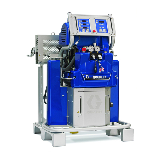
Hydraulic Variable Ratio, Heated, Plural-Component Proportioner
For spraying polyurethane foam and polyurea coatings.
Not for use in explosive atmospheres.
Important Safety Instructions
Read all warnings and instructions in this manual.
Save these instructions.
See page 3 for model information, including maximum
working pressure and approvals.
U.S. Patent Pending
Russian Patent No. 2359181
H-VR
313540L
EN
r_256886_313539_1
Advertisement
Table of Contents

Related Manuals for Graco Reactor H-VR


Summary of Contents for Graco Reactor H-VR
- Page 1 Repair - Parts H-VR 313540L Hydraulic Variable Ratio, Heated, Plural-Component Proportioner For spraying polyurethane foam and polyurea coatings. Not for use in explosive atmospheres. Important Safety Instructions Read all warnings and instructions in this manual. Save these instructions. See page 3 for model information, including maximum working pressure and approvals.
-
Page 2: Table Of Contents
E31: Pumpline reversing switch failure/high cycle Graco Information ......70 rate ....... 16 E99: Loss of communication . -
Page 3: Models
Models Models H-VR SERIES Full Load Max Flow Approximate Peak Primary Rate Output per Hydraulic Maximum Fluid Part, Amps* Per Voltage System Heater lb/min Cycle (A+B) Pressure Working Pressure Series Phase (phase) Watts† Watts (kg/min) gal. (liter) Ratio psi (MPa, bar) 256886 230V (3) 26,600 15,300... -
Page 4: Supplied Manuals
Air Supply Kit Reactor Hydraulic Proportioner Part Description Part Description 309827 Instruction-Parts Manual (English) for 313539 Reactor H-VR Proportioner, Operation Feed Pump Air Supply Kit Manual (English) Circulation and Return Tube Kits Reactor Electrical Diagrams Part Description Part Description 309852... -
Page 5: Warnings
Warnings Warnings The following warnings are for the setup, use, grounding, maintenance, and repair of this equipment. The exclama- tion point symbol alerts you to a general warning and the hazard symbol refers to procedure-specific risk. Refer back to these warnings. Additional, product-specific warnings may be found throughout the body of this manual where applicable. - Page 6 Warnings WARNING FIRE AND EXPLOSION HAZARD Flammable fumes, such as solvent and paint fumes, in work area can ignite or explode. To help prevent fire and explosion: • Use equipment only in well ventilated area. • Eliminate all ignition sources; such as pilot lights, cigarettes, portable electric lamps, and plastic drop cloths (potential static arc).
-
Page 7: Important Two-Component Material Information
Important Two-Component Material Information Important Two-Component Material Information Isocyanate Conditions Spraying or dispensing fluids that contain isocyanates creates potentially harmful mists, vapors, and atomized particulates. • Read and understand the fluid manufacturer’s warnings and Safety Data Sheet (SDS) to know specific haz- ards and precautions related to isocyanates. -
Page 8: For All Applications Except Spray Foam
Important Two-Component Material Information For all applications except spray Keep Components A and B foam Separate Cross-contamination can result in cured material in fluid Spraying or dispensing fluids that contain isocyanates lines which could cause serious injury or damage equip- creates potentially harmful mists, vapors, and atomized ment. -
Page 9: Foam Resins With 245 Fa Blowing Agents
Important Two-Component Material Information Foam Resins with 245 fa Blowing Agents Some foam blowing agents will froth at temperatures above 90°F (33°C) when not under pressure, especially if agitated. To reduce frothing, minimize preheating in a circulation sys- tem. Changing Materials NOTICE Changing the material types used in your equipment requires special attention to avoid equipment damage... -
Page 10: Temperature Control Diagnostic Codes
Temperature Control Diagnostic Codes Temperature Control Diagnostic Codes Temperature control diagnostic codes appear on tem- perature display. Code Code Name Alarm Corrective Zone Action page These alarms turn off heat. E99 clears automatically High fluid temperature Individual when communication is regained. Codes E03 through High zone current Individual No zone current with... -
Page 11: E02: High Zone Current
Temperature Control Diagnostic Codes E02: High zone current 4. Remove connector B from temperature control mod- ule, and check continuity of overtemperature switches A and B, thermocouples A and B, or FTS 1. Check hose connections for electrical short, page by measuring resistance across the pins on the plug end;... -
Page 12: E04: Fluid Temperature Sensor (Fts) Or Thermocouple Disconnected
Temperature Control Diagnostic Codes E04: Fluid Temperature Sensor E05: Circuit board overheated (FTS) or thermocouple NOTE: Each module has an on-board temperature disconnected sensor. Heat is turned off if module temperature exceeds 185°F (85°C) within the heater module. 1. Check temperature sensor connections to long green connector (B) on temperature control module, page 35. -
Page 13: Motor Control Diagnostic Codes
Pressure imbalance for causes and checks. Pressure imbalance A/W (to 3. Ensure at least one pump is in the number 1 posi- select, see tion. See Setup section of Reactor H-VR Operation page 33) manual 313539. High motor temperature Momentary loss of com- 4. -
Page 14: E24: Pressure Imbalance
Motor Control Diagnostic Codes E24: Pressure imbalance The digital display always shows the higher of the two pressures. As soon as the higher analog pres- sure drops below the lower analog pressure, the NOTE: Upon initial start-up this diagnostic code will display changes to the new higher reading. -
Page 15: E27: High Motor Temperature
Motor Control Diagnostic Codes 4. To test if the failure is with the transducer or the a. Check and clean the gun inlet screens. socket on the motor control board: b. Check and clean the gun mix chamber impinge- a. Reverse connections at J3 and J8 on the motor ment ports and center port. -
Page 16: E30: Momentary Loss Of Communication
Motor Control Diagnostic Codes E99: Loss of communication 2. Allow motor to cool completely. Check continuity between pins 1 and 2 on connector J9 on the motor control board, page 33. If the resistance is infinity, If communication is lost between the motor control dis- the motor thermal switch or the wire harness is bad. -
Page 17: Troubleshooting
Troubleshooting Troubleshooting Reactor Electronics 2. Turn main power OFF 3. Allow equipment to cool. Try the recommended solutions in the order given for Before performing any troubleshooting procedures: each problem, to avoid unnecessary repairs. Also, determine that all circuit breakers, switches, and con- 1. - Page 18 Troubleshooting PROBLEM CAUSE SOLUTION Hose display reads OA at startup. FTS disconnected or not installed. Verify proper installation of FTS (see H-VR Operation manual 313539), or adjust FTS to desired current setting. Poor display connection. Check cable connections, page 43. Replace damaged cable.
-
Page 19: Primary Heaters (A And B)
Troubleshooting Primary Heaters (A and B) 2. Turn main power OFF 3. Allow equipment to cool. Try the recommended solutions in the order given for Before performing any troubleshooting procedures: each problem, to avoid unnecessary repairs. Also, determine that all circuit breakers, switches, and con- 1. -
Page 20: Hose Heat System
Troubleshooting Hose Heat System 2. Turn main power OFF 3. Allow equipment to cool. Problems Before performing any troubleshooting procedures: Try the recommended solutions in the order given for 1. Relieve pressure, page 28. each problem, to avoid unnecessary repairs. Also, determine that all circuit breakers, switches, and con- trols are properly set and wiring is correct before assum- ing there is a problem. - Page 21 Troubleshooting PROBLEM CAUSE SOLUTION Faulty thermocouple connections. Verify that all FTS connections are snug and that pins of connectors are clean. Examine connection of ther- mocouples to long green plug on heater control board. Unplug and Erratic hose temperature. re-plug thermocouple wires, cleaning off any debris.
-
Page 22: Hydraulic Drive System
Troubleshooting Hydraulic Drive System 2. Turn main power OFF 3. Allow equipment to cool. Problems Before performing any troubleshooting procedures: Try the recommended solutions in the order given for 1. Relieve pressure, page 28. each problem, to avoid unnecessary repairs. Also, determine that all circuit breakers, switches, and con- trols are properly set and wiring is correct before assum- ing there is a problem. - Page 23 Troubleshooting PROBLEM CAUSE SOLUTION Hydraulic pump does not develop Pump is not primed or lost its prime. Check electric motor rotation. Both pressure. Low or zero pressure with motor and hydraulic pump must screeching noise. rotate counterclockwise when viewed from shaft end. If rotation is incorrect, reverse leads L1 and L2.
-
Page 24: Proportioning System
Troubleshooting Proportioning System 2. Turn main power OFF 3. Allow equipment to cool. Problems Before performing any troubleshooting procedures: Try the recommended solutions in the order given for 1. Relieve pressure, page 28. each problem, to avoid unnecessary repairs. Also, determine that all circuit breakers, switches, and con- trols are properly set and wiring is correct before assum- ing there is a problem. - Page 25 Troubleshooting PROBLEM CAUSE SOLUTION Pumps do not reverse direction or Damaged reversing switch assembly. See Pumps Do Not Reverse Direc- pumps do not move. tion, page 27. Faulty directional valve. See Pumps Do Not Reverse Direc- tion, page 27. Erratic pump movement. Pump cavitation.
- Page 26 Troubleshooting Ratio Lock Handle A Pump Arm B Pump Arm Ratio Adjustment Wheel B (Resin) A (ISO) Proportioning Proportioning Pump Pump Change Over Box Hydraulic Cylinder Reversing Switches Switch Disk r_256886_313540_4 . 1. Pump Line when viewed from rear of machine Pressure/Material Imbalance Table 2.
- Page 27 Troubleshooting Pumps Do Not Reverse Direction • verify reversing switches. Unplug the J5 reversing switch connector. Verify that 1. For the proportioning pumps to reverse direction, when the switches are not triggered there is the switch disk must contact the reversing switches. continuity between 1150-NC and Ensure that the change over box is assembled cor- 1160-T-COM, and between 1150-NC and...
-
Page 28: Repair
Repair Repair Repairing this equipment requires access to parts that may cause electric shock or other serious injury if work is not performed properly. Have a qualified elec- trician connect power and ground to main power switch terminals, see operation manual. Be sure to shut off all power to the equipment before repairing. -
Page 29: Flushing
Repair Flushing Proportioning Pumps Flush equipment only in a well-ventilated area. Do not To avoid injury and damage to pump arms and ratio spray flammable fluids. Do not turn on heaters while adjustment screws, relieve all pressure and shut off all flushing with flammable solvents. - Page 30 Repair 8. Disconnect all fluid hoses connected to pumps. 6. Turn both PRESSURE RELIEF/SPRAY valves (SA, 9. Remove pump base pin (183) and top pin (255) on both pumps. See page 58. SB) to PRESSURE RELIEF/CIRCULATION Route fluid to waste containers or supply tanks. Ensure gauges drop to 0.
-
Page 31: Circuit Breaker Module
Repair Circuit Breaker Module Table 3: Circuit Breakers, see F Ref. Size Component 1. Turn main power OFF . Disconnect power Hose/Transformer Secondary Side supply. Turn circuit breakers on to test. Transformer Primary 812A Heater A 812B Heater B 2. Relieve pressure, page 28. Motor/Pumps 3. -
Page 32: Electric Motor
Repair Electric Motor Installation 1. Place motor on unit. Removal 2. Fasten motor with screws. 3. Connect the wires, using wire nuts. Refer to the 1. Turn main power OFF . Disconnect power Reactor Electrical Diagram manual 312064 and the diagram inside the motor junction box cover. -
Page 33: Motor Control Board
Repair Motor Control Board Table 4: DIP Switch (SW2) Settings NOTE: Motor control board has one red LED (D11). Power must be on to check. See F . 6 for location. Switch ON (up) OFF (down) Function is: Switch 1 Motor soft start ON (Not applicable to •... - Page 34 Repair Motor Control 1 2 3 4 J3 (A) ti3178c-4 J8 (B) Apply 110009 thermal heatsink compound to mating surfaces. ti7724a . 6. Motor Control Board 313540L...
-
Page 35: Transducers
Repair Transducers diagnostic code follows; see E21: No component A transducer, page 13. 5. If transducer fails test, thread cable through top of 1. Turn main power OFF . Disconnect power cabinet. Note path as cable must be replaced in same way. -
Page 36: Temperature Control Module
Repair Temperature Control Module Table 6: Temperature Control Module Connections Connector Description DATA (A) Data reporting HOSE T/C P; FTS (purple) HOSE T/C R; FTS (red) HOSE T/C S; FTS (silver (unshielded bare wire)) HEATER T/C B, Y; Thermocouple (yellow) SENSOR (B) HEATER T/C B, R;... - Page 37 Repair Test SCR Circuit Replacing Temperature Control Assembly Modules 1. Test the SCR circuit in the on position: NOTICE a. Make sure everything is connected, including Before handling assembly, put on a static conductive the hose. wrist strap to protect against static discharge which can damage assembly.
-
Page 38: Primary Heaters
Repair Primary Heaters 6. To remove heater element, first remove thermocou- ple (410) to avoid damage, see step 7, page 39. Heater Element 7. Remove heater element (407) from housing (401). Be careful not to spill any fluid left in housing. 8. - Page 39 Repair 8. Replace thermocouple, F . 10. Thermocouple a. Remove protective tape from thermocouple tip (T). 1. Turn main power OFF . Disconnect power b. Apply PTFE tape and thread sealant to male supply. threads and tighten thermocouple housing (H) 2.
-
Page 40: Heated Hose
Repair Overtemperature Switch 5. If hose fails test, retest at each length of hose, including whip hose, until failure is isolated. Check FTS Cables 1. Turn main power OFF . Disconnect power supply. 1. Turn main power OFF . Disconnect power 2. -
Page 41: Fluid Temperature Sensor (Fts)
Repair Fluid Temperature Sensor (FTS) 4. If FTS fails any test, replace FTS. 5. Disconnect air hoses (C, L), and electrical connec- Test/Removal tors (D). 6. Disconnect FTS from whip hose (W) and fluid hoses 1. Turn main power OFF . - Page 42 Repair Transformer Primary Check 3. To verify transformer voltage, turn on hose zone. Measure voltage from 18CB-2 to POD-HOSE-P15-2; see Reactor Electrical Dia- grams manual 312064. 1. Turn main power OFF Model Secondary Voltage 2. Locate the two smaller (10 AWG) wires coming out of transformer.
-
Page 43: Display Module
Repair Display Module Red Stop Button NOTICE Temperature and Pressure Displays Before handling board, put on a static conductive wrist strap to protect against static discharge which NOTICE can damage board. Follow instructions provided with Before handling board, put on a static conductive wrist strap. - Page 44 Repair Apply medium strength thread sealant. ti2574a Detail of Membrane Switches and Display Boards Temperature Display Pressure Display 502c 502a 502b 501c 501a 501b ti3172a . 14. Display Module 313540L...
-
Page 45: Inlet Fluid Strainer Screen
Repair Inlet Fluid Strainer Screen 161c The inlet strainer at each proportioning pump filters out solid matter that can plug the inlet check valves. Inspect the screens daily as part of the startup routine, and clean as required. Isocyanate can crystallize from moisture contamination or from freezing. - Page 46 Repair 3. Place a pan under reservoir drain plug (110k) to 5. Place a rag around base of oil filter (135) to prevent catch oil. oil from spilling. Unscrew filter 1/4-3/4 turn to break air lock in filter. Wait five minutes to allow oil in filter to drain back into reservoir.
- Page 47 Repair Table 9: Approved Anti-Wear (AW) Hydraulic Oils Supplier Name Citgo A/W ISO Grade 46 Amsoil AWI ISO Grade 46 (synthetic*) BP Oil International ® Energol HLP-HM, ISO Grade 46 Carl Bechem GmbH Staroil HVI 46 Castrol Hyspin AWS 46 Chevron ®...
-
Page 48: Parts
Parts Parts 42 See page 54 See page 53 See page 53 See page 54 See page 51 See page 61 ti9831a 313540L... - Page 49 Parts 185, 186, 187 174 146 See page 50 See page 55 r_256886_313540_2 313540L...
- Page 50 Parts Pump Assembly Overview See page 58 See page 58 See page 59 183, 184 195, 196, 197 r_256886_313540_4 313540L...
- Page 51 Parts Detail of Cabinet Area 25, 147 See page 52 54 TI9834a 313540L...
- Page 52 Parts Left Side of Cabinet 55, 56 TI9835a 8 (Ref) Right Side of Cabinet 103 (Ref) TI9836a 313540L...
- Page 53 Parts Detail, Fluid Manifold Area 7, see page 64 717 (Ref) 111 (Ref) TI9838a Detail, Proportioner Area 111 (Ref) See page 60 313540L...
- Page 54 Parts Detail, Electric Motor Area 111 (Ref) 118 (Ref) ti7709a Detail, Hydraulic Reservoir Area 111 (Ref) 119, 120 111 (Ref) 115 60 133 125 142, 143 See page 55 See page 51 1 (Ref) TI9832b 313540L...
- Page 55 Parts Ref. 161, Fluid Inlet Kit 161d 161a 161b 161c 161d r_256886_313540_7 Ref. 110, Hydraulic Reservoir 110f 110m 110b 110c 110d 110k 110j ti9840a 313540L...
- Page 56 Parts Parts Ref. Part Description Ref. Part Description 58 STRAP, tie, wire 247813 HEATER 111800 SCREW, cap, hex hd 247785 MOTOR 247782 SPACER 245974 DISPLAY; see page 62 247850 COVER, front CONTROL, temperature; see page 117284 GRILL, fan guard 68† 117553 SWITCH, added pole 247835 BOARD, circuit, motor control 74...
- Page 57 Parts Ref. Part Description Ref. Part Description 247856 PULLEY, fan GC2108 WASHER, lock, spring, #10 15H512 LABEL, control GC2188 SCREW, socket hd 15H204 KNOB, pressure GC0530 LABEL, calibration, right 117560 SCREW, set, socket hd GC0531 LABEL, calibration, left 247793 HOSE, inlet, coupled GC0541 KNOB, clamping 255029 GAUGE, pressure, fluid, panel GC1196 FITTING, lube;...
-
Page 58: Sub Assemblies
Parts Sub Assemblies Pump Assembly Pump Detail (A Side Pump Shown) see manual 313485 275 or 276 Apply blue Loctite and torque to 250 ft-lbs (337.5 N•m). r_256886_313540_5 Apply blue Loctite and torque to 15 ft-lbs (20.3 N•m). 313540L... - Page 59 Parts Air Motor Detail Apply blue Loctite and torque to 250 ft-lbs (337.5 N•m). r_256886_313540_8 Ref. Part Description Ref. Part Description GC2041 WASHER, flat, std; 1/2 in. GC1132 EXTENSION, stndoff, change over GC2112 WASHER, lock, spring;1/2 in, GC2107 WASHER, lock, spring; #8 159239 NIPPLE, pipe GC2194 SCREW, shdc;...
-
Page 60: Hydraulic Directional Valve Assembly
Parts Hydraulic Directional Valve Assembly r_256886_313540_6 Proportioner Assembly Ref. Part Description Ref. Part Description 295225 PLUG, pipe, flush 106258 O-RING 255037 ELBOW; 3/4 nptf 298040 MANIFOLD, hydraulic 255038 CONNECTOR 113467 SCREW, socket head 15H184 WIRE, bi-directional cable, assy. 120299 VALVE, directional, hydraulic 15H253 HOSE, gauge, hydraulic, 3000 psi C19986 SCREW, socket head 121309 CONNETOR;... -
Page 61: 7.65 Kw Single Zone Heater
Parts 7.65 kW Single Zone Heater (Two Per Machine) Part 247813 r_247813_312063 Apply 110009 thermal heatsink compound. Ref. Part Description Ref. Part Description 117484 SENSOR HOUSING, heater 100518 SCREW, machine, pan hd 121309 ADAPTER, 3/4 SAE-ORB x 15H305 PLUG, hollow 1/2 in. -
Page 62: Display
Parts Display 20 (Ref) ti2574a 502a 502c 502b 501c 501a 501b ti3172a Ref. Part Description Ref. Part Description 15B292 COVER 245978 DISPLAY, pressure; includes 15B291 PLATE 501a-501c 246287 HARNESS, wire, red stop button 501a 246130 .BOARD, circuit 117499 HANDLE 501b 246478 .SWITCH, membrane 117523 NUT, cap;... -
Page 63: Temperature Control
Parts Temperature Control To B Heater Module To A Heater Module To Hose Heater Module TI9843a Ref. Part Description 247772 PANEL, module mounting 247827 HOUSING, control module 247828 HOUSING, heater module 115942 NUT, hex 247801 CABLE, communication 247825 KIT, cover, connector with screws 313540L... -
Page 64: Fluid Manifold
Parts Fluid Manifold Torque to 355-395 in-lb (40.1-44.6 N•m). Apply sealant (113500) to threads. Valve must be closed with handle position as shown on drawing. ** Apply PTFE tape or thread sealant to tapered threads. 702a 702b TI9839b Ref. Part Description Ref. -
Page 65: Circuit Breaker Modules
Parts Circuit Breaker Modules A - 230V, 3 Phase Circuit Breaker Modules For wiring and cable connections, refer to electrical dia- grams manual 312064, supplied. See page 66 for parts. 803, 804 168BR 172CB 178CB 187CB 197CB B - 400V, 3 Phase Circuit Breaker Modules For wiring and cable connections, refer to electrical dia- grams manual 312064, supplied. - Page 66 Parts Circuit Breaker Modules Parts List Breaker Modules Ref. Description 230V, 3 phase 400V, 3 phase 255028 255028 RAIL, mounting 255045 255045 CLAMP, block, end 255043 255043 HOLDER, fuse terminal, block 255023 255023 FUSE 255042 255042 TERMINAL, block 255044 255044 BRIDGE, plug in, jumper 255046 255046...
-
Page 67: Dimensions
Dimensions Dimensions Dimension in. (mm) Dimension in. (mm) D (front and rear mounting holes) 32.5 (825.5) A (height) 57.3 (1455.4) F (side mounting holes) 30.4 (771.6) B (width) 37.9 (961.6) G (mounting post inner diameter) 0.44 (11.2) C (depth) 33.0 (838.2) Top View r_256886_313539_1 Front of Machine... -
Page 68: Technical Data
Technical Data Technical Data Category Data Maximum Fluid Working Pressure 3500 psi (24.1 MPa, 241 bar) Fluid Inlets 3/4 npsm union in 1 in. npt(f) ball valve Fluid Outlets Component A (ISO): #8 (1/2 in.) JIC, with #5 (5/16 in.) JIC adapter Component B (RES): #10 (5/8 in.) JIC, with #6 (3/8 in.) JIC adapter Fluid Circulation Ports 1/4 npsm(m), with plastic tubing, 250 psi (1.75 MPa, 17.5 bar) maximum... -
Page 69: Notes
Notes Notes 313540L... -
Page 70: Graco Standard Warranty
With the exception of any special, extended, or limited warranty published by Graco, Graco will, for a period of twelve months from the date of sale, repair or replace any part of the equipment determined by Graco to be defective.