
Related Manuals for Stanley FG10


Summary of Contents for Stanley FG10
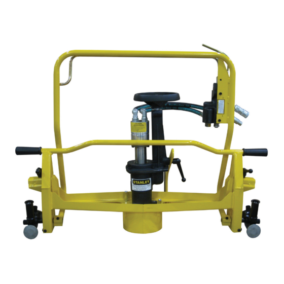
- Page 1 FG10 HYDRAULIC FROG GRINDER PG05 HYDRAULIC PROFILE GRINDER USER MANUAL Safety, Operation and Maintenance © 2017 STANLEY Black & Decker, Inc. New Britain, CT 06053 U.S.A. 28072 8/2018 Ver. 15...
-
Page 3: Table Of Contents
REPAIRS AND / OR SERVICE TO THIS TOOL MUST ONLY BE DONE BY AN AUTHORIZED AND CERTIFIED DEALER. For the nearest certified dealer, call STANLEY Infrastructure at (503) 659-5660 and ask for a Customer Service Representative. FG10 User Manual ◄ 3... -
Page 4: Safety Symbols
Always observe safety symbols. They are included for your safety and for the protection of the tool. LOCAL SAFETY REGULATIONS Enter any local safety regulations here. Keep these instructions in an area accessible to the operator and maintenance personnel. 4 ► FG10-PG05 User Manual... -
Page 5: Safety Precautions
• Keep the wheel off all surfaces when starting the The FG10 Hydraulic Frog Grinder and PG05 Profile grinder. Grinder will provide safe and dependable service if operated in accordance with the instructions given in •... -
Page 6: Tool Stickers & Tags
SEE OTHER SIDE SEE OTHER SIDE removal. We suggest you retain this tag and attach it to the tool when not in use. SAFETY TAG P/N 15875 (Shown smaller then actual size) 6 ► FG10-PG05 User Manual... -
Page 7: Hose Types
This hose is not certifi ed non-conductive and must never be used near electrical conductors. HOSE SAFETY TAGS To help ensure your safety, the following DANGER tags are attached to all hose purchased from STANLEY. DO NOT REMOVE THESE TAGS. - Page 8 HOSE RECOMMENDATIONS 8 ► FG10-PG05 User Manual...
- Page 9 2000 psi 2000 psi (At the power supply outlet) (172 bar) (138 bar) (138 bar) (138 bar) (138 bar) Note: These are general hydraulic system requirements. See tool specifi cation page for tool specifi c requirements. FG10-PG05 User Manual ◄ 9...
-
Page 10: Operation
It may turning the strap wrench while holding the wrench be necessary to rotate the entire grinder 180 degrees provided. and place it on the other side of the point in order to 10 ► FG10/PG05 User Manual... - Page 11 (61) and clamping it in place by turning the adjustable handle (44). CONNECTING THE HOSES 1. Wipe all hose couplers with a clean lint-free cloth before making connections. 2. Connect the hoses from the hydraulic power source FG10/PG05 User Manual ◄ 11...
- Page 12 5. To grease between main housing bore (item 73) and the ram outer diameter (item 26), 1 - 2 pumps of grease are required at these locations. Too much grease will lockup the feed assembly (See figure 4 below). Figure 4 12 ► FG10/PG05 User Manual...
-
Page 13: Tool Protection & Care
This can cause damage to internal seals. • Always replace hoses, couplings and other parts with replacement parts recommended by STANLEY. Supply hoses must have a minimum working pressure rating of 2500 psi/172 bar. FG10/PG05 User Manual ◄ 13... -
Page 14: Troubleshooting
Inspect, repair or replace. Flow control malfunctioning. Have flow control serviced at an authorized STANLEY service center. Grinder operates too fast. Flow control malfunctioning. Have flow control and valve body serviced at an authorized STANLEY service center. 14 ► FG10/PG05 User Manual... -
Page 15: Specifications
Declared vibration emission value in accordance with EN 12096 Measured vibration emission value: a 2.0 m/sec² Uncertainty: K 0.5 m/sec² Values determined according to ISO 8662-4, ISO 5349-1,2 ACCESSORIES 6 x 3 x 5/8-11 Thread Cup Stone ........................28597 FG10/PG05 User Manual ◄ 15... -
Page 16: Fg10 - Pg05 Parts Illustration
FG10 - PG05 PARTS ILLUSTRATION FG10 FROG GRINDER and PG05 PROFILE GRINDER Wheel Pivot Assy P/N- 26085 Shown Here Includes the following: 26087 Assy, 26088 Assy, 26089 Assy and Items 84, 86, 77 & 78. Assemblies below are shown with dotted lines around them in the above exploded view. - Page 17 FG10 - PG05 PARTS ILLUSTRATION Connect to 99 NO. 128 IS SHIPPED LOOSE FOR GRINDING WHEEL INSTALLATION/REMOVAL Connect to NOTE Some pf the following item numbers are not included in the light weight model of the PG05 Profile Grinder. Extension Assembly Insert Between and Frame.
-
Page 18: Fg10 Parts List
00635 01607 SET SCREW 26059 PIVOT PIN ASSY 02179 00899 CAPSCREW 26809 HAND WHEEL 26831 WASHER 25287 WIPER • 06989 O-RING, -018 • 27748 BUSHING 26090 BUSHING 27749 HOUSING 17668 ROLL PIN 02900 ROLL PIN 18 ► FG10-PG05 User Manual... - Page 19 FLOW CONTROL (PRE-SET) 01411 O-RING, .488 X .624 X .078 -906 • 20145 STEEL BALL 25005 VALVE BLOCK 03787 GPM DECAL (US MODELS ONLY) 00144 CAPSCREW 25842 WRENCH (TAPED TO FRAME) 26142 EXTENSION BRACKET WELDMENT FG10-PG05 User Manual ◄ 19...
-
Page 20: Pg05 Parts List
O-RING, -018 • 27941 SPINDLE 26090 BUSHING 00772 WOODRUFF KEY 25278 RETAINING RING 25280 OIL SEAL, 1.250 X 2.047 X .299 • 25419 DRIVE FLANGE 01607 SET SCREW 02179 26809 HAND WHEEL 25287 WIPER • 20 ► FG10-PG05 User Manual... - Page 21 18008 SPRING WASHER 24819 SPRING 17904 RETAINING RING 00955 PIPE PLUG 24289 PLUG 28914 FLOW CONTROL (PRE-SET) 01411 O-RING, .488 X .624 X .078 -906 • 20145 STEEL BALL 25005 VALVE BLOCK 03787 GPM DECAL FG10-PG05 User Manual ◄ 21...
-
Page 22: Spark Guard & Inner Guard
NYLOCK NUT 29920 CAPSCREW 02259 WASHER 69755 SPARK GUARD 69767 SPARK SCREEN 69772 SPARK GUARD ASSY (INCLUDES ITEMS 1 THRU 5) Inner Guard Note: Items in this view can be found on the main parts list. 22 ► FG10-PG05 User Manual... - Page 24 STANLEY Infrastructure 6430 SE Lake Road Portland, Oregon 97222 USA (503) 659-5660 / Fax (503) 652-1780 www.stanleyinfrastructure.com...