Table of Contents
Advertisement
Quick Links
Manual
enAble
Powerchair Control System
Read Instructions Carefully!
Specifications are subject to change without notice.
© 2011 Curtis Instruments, Inc. ® Curtis is a registered trademark of Curtis Instruments, Inc.
© The design and appearance of the products depicted herein are the copyright of Curtis Instruments, Inc.
40
®
Curtis Instruments, Inc.
200 Kisco Avenue
Mt. Kisco, NY 10549
www.curtisinstruments.com
37893 Rev E 12/11
Advertisement
Chapters
Table of Contents

Summary of Contents for Curtis enAble 40
- Page 1 Specifications are subject to change without notice. © 2011 Curtis Instruments, Inc. ® Curtis is a registered trademark of Curtis Instruments, Inc. © The design and appearance of the products depicted herein are the copyright of Curtis Instruments, Inc. 37893 Rev E 12/11...
-
Page 3: Table Of Contents
Sound & Display Parameters ..........27 Handcontrol Inhibit Parameters ........27 Seat Parameters ..............28 Lights Parameters ..............29 Current Limits Parameters ..........29 Multi-Function Input 1 Parameters ........30 Multi-Function Input 2 Parameters ........31 Multi-Function Input 3 Parameters ........32 Curtis enAble 40 Manual, ® Rev. E... - Page 4 6. MONITOR MENU ..............36 7. TUNING GUIDE..............38 8. DIAGNOSTICS & TROUBLESHOOTING ......47 9. MAINTENANCE ..............52 Guidelines for BDI Setup APPENDIX A Curtis WEEE / RoHS Statement APPENDIX B Programming Devices APPENDIX C Mating Connectors & Replacement Parts APPENDIX D enAble ®...
- Page 5 TABLES Handcontrol (1741) diagnostics ........... 48 TABLE Attendant control (1742) diagnostics ........51 TABLE E-1: Specifications, 1740 powerbase ...........E-1 TABLE E-2: Specifications, 1741 handcontrol ........E-1 TABLE E-3: Specifications, 1742 attendant control ........E-1 TABLE Curtis enAble 40 Manual, ® Rev. E...
-
Page 7: Overview
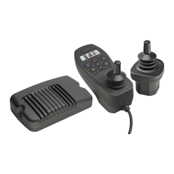
Powerchair Control System: powerbase (1740), user handcontrol (1741), attendant control (1742). Like all Curtis motor control products, the enAble 40 system offers superior ® control of drive performance, delivering a ride that is smooth and responsive in all modes: acceleration, deceleration, forward or backward, on smooth indoor surfaces, up a hill, or over gravel. -
Page 8: Configurations
✔ Powerbase software is upgradable in the field or in the factory. ✔ Onboard or offboard charging up to 8 amps accommodates high capacity batteries. ✔ Compatible with the Curtis 1313 handheld programmer and 1314 PC Programming Station. User handcontrol: ✔... -
Page 9: Profiles
Some need only “indoor” and “outdoor” modes while other users prefer to use three or four different speed modes just around the normal walking pace to make travel with pedestrian friends and family easier. Curtis enAble 40 Manual, ®... -
Page 10: Multi-Function Inputs
Familiarity with your Curtis enAble ® Powerchair Control System will help you install and operate it properly. We encourage you to read this manual carefully. If you have questions, please contact the Curtis office nearest you. Curtis enAble 40 Manual, ®... -
Page 11: Installation And Wiring
The powerbase is easily mounted to the chair by means of two bolts, and can be oriented in any position. Fig. 2 Mounting dimensions, Curtis 1740 powerbase. Dimensions in millimeters (and inches) A groove on the underside of the powerbase simplifies alignment when the powerbase is mounted on a tube, and provides stability. - Page 12 Brass inserts in the user handcontrol allow it to be securely mounted and re- moved/reinstalled many times. The handcontrol is designed to fit both tube and plate mounting systems. Fig. 3 Mounting dimensions, Curtis 1741 user handcontrol. Dimensions in millimeters (and inches) Curtis enAble 40 Manual, ®...
- Page 13 Like the handcontrol, the attendant control has brass inserts that allow it to be securely mounted and removed/reinstalled many times. The field replaceable cable can be rotated to either of two positions, fore and aft. Fig. 4 Mounting dimensions, Curtis 1742 attendant control. Dimensions in millimeters (and inches) Curtis enAble 40 Manual, ®...
-
Page 14: Powerbase Wiring
40 system and must be purchased directly from your Curtis dealer or sales representative. The electrical connectors are standard AMP parts. Curtis also provides a kit with all the parts required to connect the high power wiring to the powerbase. See Appendix D for part numbers. -
Page 15: Fig. 6 Wiring For The Multi-Function Inputs
2 — INSTALLATION & WIRING Fig. 6 Wiring for the Multi-Function inputs. Molex High Current Contacts must be used for onboard charging through this connector. Allowable current is 8 amps continuous. Curtis enAble 40 Manual, ® Rev. E... -
Page 16: Connecting The Control Modules
Pin 5 RXD Allowable current for a charger in this port is 8 amps continuous. The inhibit pin (pin 3) halts all chair travel during charging. Additionally, it can prevent specific actuator movements. Curtis enAble 40 Manual, ® Rev. E... -
Page 17: User Handcontrol (1741)
(8 buttons): on/off, horn, speed up, speed down, L turn, R turn, headlights, mode. ■ ■ ■ ■ ■ ■ ■ ■ The functions of the various buttons are described in the following pages. Curtis enAble 40 Manual, ® Rev. E... - Page 18 Pressing the Speed Down button selects the next lower speed mode each time it is pressed, while pressing the Speed Up button selects the next higher speed mode. The speed modes function like incremental positions on a variable speed pot. Curtis enAble 40 Manual, ® Rev. E...
- Page 19 The Hazard Lights button activates the hazard lights: i.e., flashing left and right turn signals, front and rear. They will continue to flash even if the system is powered down. Pressing the button again turns them off. Curtis enAble 40 Manual, ®...
- Page 20 MODE 1 MODE 2 MODE 1 AND MODE 2 BUTTON ( ) BUTTON ( ) BUTTONS ( + ) PRESSED PRESSED PRESSED Curtis enAble 40 Manual, ® Rev. E...
- Page 21 In this example, Actuator Mode 1 is the seatback, Actuator Mode 2 is both legs, and Simultaneous Mode is programmed On. See Seat menu, page 28. MODE BUTTON JOYSTICK MOVED JOYSTICK MOVED PRESSED TO RIGHT TO RIGHT AGAIN (MODE 1) (MODE 2) (MODES 1+ 2) Curtis enAble 40 Manual, ® Rev. E...
-
Page 22: Lcd Display
If there is a problem, the Warning icon will light and the Turn Signal indicator will flash at twice its normal rate. The Attendant Control icon is lit continuously when the chair is under attendant control. Curtis enAble 40 Manual, ® Rev. E... -
Page 23: Attendant Control (1742)
Drive mode was last active). Drive speed is limited by Attendant Speed 1 or 2 (see Speed Mode menu, page 25). A short press on the Mode button toggles between Attendant Speed Modes 1 and 2. Curtis enAble 40 Manual, ®... -
Page 24: Indicator Leds
The user can control the lights and horn, but not the drive and seat functions. The Attendant Takeover parameter determines whether the user hand- control can power down the system when both controls are active. Curtis enAble 40 Manual, ®... -
Page 25: Programmable Parameters
® 40 Powerchair Control System has a number of parameters that can be programmed using a Curtis 1313 handheld programmer or Curtis 1314 PC Programming Station. The programmable parameters allow the vehicle’s performance to be customized to fit the needs of specific applications. -
Page 26: Configuration Parameter And Mychair Parameter
(Configuration and MyChair), as the profile can be set at any of eleven points along the profile continuum. This provides tremendous versatility without the need for customizing any of the other parameters. Curtis enAble 40 Manual, ® Rev. E... -
Page 27: Drive Parameters (Profiles 1&2)
0 provides deceleration at the normal rate, and a setting of 100 provides the fastest possible stop. Emergency Stop 1–100 % Deceleration rate applied at key-off or in the event of a fault. Curtis enAble 40 Manual, ® Rev. E... -
Page 28: Steer Parameters (Profiles 1&2)
Speed No Turn must be set higher than Speed Full Turn. Curtis enAble 40 Manual, ®... -
Page 29: Fig . 11: Electronic Gating, Using The Gate Shape Parameter
5 — PROGRAMMABLE PARAMETERS: Steer Parameters (for Profiles 1&2) Fig. 11 Electronic gating, using the Gate Shape parameter. Fig. 12 Dynamic turn radius control, using the patent-pending Speed Full Turn and Speed No Turn parameters. Curtis enAble 40 Manual, ® Rev. E... -
Page 30: Handcontrol Parameters
When this parameter is set to 1, the attendant control is in command and the handcontrol cannot power down the system. When this parameter is set to 2, the user handcontrol can power down the system even when the attendant control is on. Curtis enAble 40 Manual, ® Rev. E... -
Page 31: Speed Mode Parameters
Speed limit setting for Speed Mode 9. Attendant Speed 1 0–100 % Speed limit setting for Attendant Speed Mode 1. Attendant Speed 2 0–100 % Speed limit setting for Attendant Speed Mode 2. Curtis enAble 40 Manual, ® Rev. E... -
Page 32: Joystick Parameters
Turn on the system with the attendant control; do not turn on the user handcontrol. Follow the same procedure as for calibrating the user handcontrol joystick. When calibrating the attendant control joystick, the beeps are replaced with flashing green LEDs in the chair icon. Curtis enAble 40 Manual, ® Rev. E... -
Page 33: Sound & Display Parameters
Actuator 1 will be halted in the positive direction. Halt Act 2 Dir- On/Off Actuator 2 will be halted in the negative direction. Halt Act 2 Dir+ On/Off Actuator 2 will be halted in the positive direction. Curtis enAble 40 Manual, ® Rev. E... -
Page 34: Seat Parameters
Actuator Stop Time 3–120 sec The actuator shuts off if it runs longer than this time. Actuator Open Detect 0–4.2 A An actuator fault is detected if the current falls below this level. Curtis enAble 40 Manual, ® Rev. E... -
Page 35: Lights Parameters
Sets the motor current limit during normal driving. Brake Current Limit 25–60 A Sets the motor current limit during regen braking. The current limit range maxes out at 50 A for 50-amp controllers. Curtis enAble 40 Manual, ® Rev. E... -
Page 36: Multi-Function Input 1 Parameters
Sets the speed limit when the input is low or the potentiometer wiper is fully to B-. Speed Limit High 0–100 % Sets the speed limit when the input is high or the potentiometer wiper is at 100K to B-. Curtis enAble 40 Manual, ® Rev. E... -
Page 37: Multi-Function Input 2 Parameters
Actuator 2 will be halted in the negative direction. Halt Act 2 Dir+ On/Off Actuator 2 will be halted in the positive direction. Speed Limit 0–100 % Sets the speed limit that will be in effect when Input 2 is active. Curtis enAble 40 Manual, ® Rev. E... -
Page 38: Multi-Function Input 3 Parameters
Actuator 2 will be halted in the positive direction. Speed Limit 0–100 % Sets the speed limit that will be in effect when Off/Swvl/Seat = 2 and Input 3 is active (see Active Low parameter). Curtis enAble 40 Manual, ® Rev. E... -
Page 39: Compensation Parameters
Sets the maximum battery voltage that can be applied to the motor. Volts Headroom 0–4.0 V Amount of spare voltage reserved for steering inputs at full speed, or when climbing ramps or curbs. Curtis enAble 40 Manual, ® Rev. E... -
Page 40: Motors & Brakes Parameters
A gear softening value of 100% provides maximum softening, and a value of 0% eliminates the feature. Single Brake Drive On/Off Allows using only the M1 brake output to drive two 12V brakes in series. Curtis enAble 40 Manual, ® Rev. E... -
Page 41: Battery Parameters
Discharge rate of the battery. Larger values are for larger batteries, which discharge more slowly. Charge Factor 1–100 Charge rate of the battery. Larger values are for larger batteries, which charge more slowly Curtis enAble 40 Manual, ® Rev. E... -
Page 42: Lights
-37.5 – +37.5 V Voltage applied to Actuator Motor 1. Actuator 2 Voltage -37.5 – +37.5 V Voltage applied to Actuator Motor 2. Actuator Current -12.0 – +12.0 A Current through the actuator motors. Curtis enAble 40 Manual, ® Rev. E... - Page 43 Mode parameter (see page 35) is On. BAT TE RY • • • Battery Voltage 0–38.5 V Voltage of the main battery. BDI % 0–100 % Battery state-of-charge as estimated by the powerbase. Curtis enAble 40 Manual, ® Rev. E...
-
Page 44: Tuning Guide
(Program > Motors & Brakes menu). 3. For now, set Extra Uphill Comp = 0 and Downhill Gain = 0 STEP (Program > Motor Controller > Compensation menu). You will tune these parameters later. Curtis enAble 40 Manual, ® Rev. E... - Page 45 5. Push the joystick full forward, driving the chair hard against the STEP object or wall, and note the M1 and M2 Resistance values. 6. Set the M1 and M2 Resistance parameters to these monitored STEP values. Curtis enAble 40 Manual, ® Rev. E...
- Page 46 1. Set the MyChair parameter to 1.0, which is Profile 1. Later, after STEP Profile 2 has also been defined, MyChair can be set to Profile 1, to Profile 2, or to a point between; see page 3. Curtis enAble 40 Manual, ® Rev. E...
- Page 47 Adjust the Rev Decel High Speed parameter to provide the required stopping distance. 7. Use the keypad to select the slowest speed mode. STEP 8. Repeat Steps 2–6 for the corresponding low speed parameters. STEP Curtis enAble 40 Manual, ® Rev. E...
- Page 48 Again, driving from full turn to full straight and back should provide a consistent speed feel. Curtis enAble 40 Manual, ® Rev. E...
- Page 49 3. The speed at which the chair enters a turn greatly impacts the STEP tuning of the accel and decel turning rates. The enAble 40 system has two features that can be used to slow the chair down or restrict turning as a function of speed: Gate Shape and Dynamic Turn Radius Control (see Figures 11 and 12, page 23).
- Page 50 This parameter is greatly affected by the chair’s drive wheel configuration. Rear-wheel-drive chairs typically need the highest adjustments, while mid-wheel- and front-wheel-drive chairs are naturally sensitive and require a lower setting. Curtis enAble 40 Manual, ® Rev. E...
- Page 51 3. Increase the Anti-Rollback Comp parameter and repeat the test. STEP Continue until it feels like the chair is being restricted when rolling backward. The Anti-Rollback Comp parameter must be Curtis enAble 40 Manual, ® Rev. E...
- Page 52 7. After adjusting the thresholds, it is necessary to go back to the STEP ramp and verify and possible re-tune some of the uphill or down- hill parameters. Repeat steps 2 through 6 until you are satisfied with both ramp and flat floor performance. Curtis enAble 40 Manual, ® Rev. E...
-
Page 53: Diagnostics & Troubleshooting
Faults menu to find more information about the precise fault that is occurring. The problem may be as simple as a loose connection or faulty wiring that can be easily fixed. Curtis enAble 40 Manual, ®... -
Page 54: Table 1: Handcontrol (1741) Diagnostics
Leg Actuator Driver Fault. 1. Select drive or a different actuator; fault may clear. 2. Check wiring. 3. Check that the leg rest is not jammed. 4. Check actuator; replace if faulty. 5. Replace powerbase. Curtis enAble 40 Manual, ® Rev. E... - Page 55 3. If fault continues, check wiring. Speed Limit Warning. 1. Return seat to normal or upright position. 2. If fault continues, check all limit switches and wiring. The numerical icon showing the present Speed Mode flashes. Curtis enAble 40 Manual, ® Rev. E...
- Page 56 Battery charging; inhibit. 1. Unplug charger when charging is complete. The bars on the battery icon light up in a chase sequence. These icons indicate a problem only if they appear when they shouldn’t. Curtis enAble 40 Manual, ® Rev. E...
-
Page 57: Table 2: Attendant Control (1742) Diagnostics
All the chair Actuator Over/Under Temperature See Table 1. LEDs flashing Warning. BDI LED Flashing Red Undervoltage. See Table 1. Flashing Green Overvoltage. See Table 1. Flashing Red, Charging battery; inhibit. Amber, Green in Sequence Curtis enAble 40 Manual, ® Rev. E... -
Page 58: Maintenance
9 — MAINTENANCE MAINTENANCE There are no user serviceable parts in the Curtis 1740 controller. No attempt should be made to open, repair, or otherwise modify the controller. Doing so may damage the controller and will void the warranty. Replacement parts are, however, available for the Curtis 1741 user hand- control and Curtis 1742 attendant control. - Page 59 2.a Select a medium speed mode and drive the chair for 10 to 15 minutes. 2.b After this time and while driving straight on a level surface, record the battery voltage displayed in the 1311’s Monitor menu. 2.c Set the Full Voltage parameter to this value. Curtis enAble 40 Manual, ® Rev. E...
- Page 60 BDI gauge until the battery is full. The enAble 40 can also be set to allow the user to stop the charge in mid-cycle and display a proportional amount of charge, or “partial charge”...
- Page 61 Using the Charge Factor setting, calculate the time it should take to reach 50% charge (50% time = Charge Factor / 20). After the calculated 50% time, stop the charger and turn on the enAble 40 system. Plug in the 1311 and read the BDI% off the Monitor menu.
- Page 62 The requirement to mark equipment with the WEEE symbol (the crossed-out wheeled bin) went into effect as of August 13, 2005. As of this date, Curtis In- struments began the process of marking all products that fall within scope of this directive with the WEEE symbol, as shown opposite.
- Page 63 Curtis firmly believes that the operating environments, safety requirements, and reliability levels required of automotive electronics are directly analogous to that of our speed controller products. As such, Curtis will not be switching to a lead-free solder process until lead-free solder pastes and techniques are available that meet the requirements of the RoHS study groups and ELV Automotive In- dustry bodies.
- Page 64 APPENDIX C: PROGRAMMING DEVICES APPENDIX C PROGRAMMING DEVICES Curtis programmers provide programming, diagnostic, and test capabilities for the enAble 40 system. The programmer plugs into the 5-pin connector on the ® user handcontrol; power is supplied by the powerbase. When the programmer powers up, it gathers system information from the powerbase.
- Page 65 APPENDIX D: CONNECTORS & PARTS LIST APPENDIX D MATING CONNECTORS & REPLACEMENT PARTS High Power Connectors, 1740 Powerbase Complete battery and motor connector kit Curtis p/n 381570001 The kit contains: 2 Motor connector housings Curtis p/n 37383 1 Battery connector housing...
- Page 66 2.95" × 3.3" × 4.98" Height is to top of joystick) Height is to top of joystick) MODEL NUMBER OPTIONS MODEL NUMBER OPTIONS 1741-20XX — 1742-20XX — 1741-21XX lights 1741-22XX actuators 1741-23XX actuators & lights Curtis enAble 40 Manual, ® Rev. E...