
Related Manuals for Peavey IPR2 5000


Summary of Contents for Peavey IPR2 5000
- Page 1 IPR2 ™ 5000/7500 IPR2 ™ 5000/7500 DSP Power Amplifiers Operating Operat ting Manual Manu www.peavey.com...
- Page 2 a risk of electric shock to persons. Intended to alert the user of the presence of important operating and maintenance (servicing) instructions in the literature accompanying the product. CAUTION: Risk of electrical shock — DO NOT OPEN! CAUTION: WARNING: Protective earthing terminal. The apparatus should be connected to a mains socket outlet with a protective earthing connection. Este símbolo tiene el propósito de alertar al usario de la presencia de instruccones importantes sobre la operación y mantenimiento en la información que viene con el producto.
-
Page 3: Important Safety Instructions
IMPORTANT SAFETY INSTRUCTIONS WARNING: When using electrical products, basic cautions should always be followed, including the following: Read these instructions. Keep these instructions. Heed all warnings. Follow all instructions. Do not use this apparatus near water. Clean only with a dry cloth. Do not block any of the ventilation openings. - Page 4 Logo referenced in Directive 2002/96/EC Annex Logotipo al que se hace referencia en la Directiva 2002/96/EC Logo documenté dans l’annexe de la Directive 2002/96/EC La barra es el símbolo para marcar los nuevos desechos y se aplica The bar is the symbol for marking of new waste and is applied La barre est le symbole de signalisation des nouveaux déchets qui Correct Disposal of this product.
- Page 5 FCC Compliancy Statement This equipment has been tested and found to comply with the limits for a Class A digital device, pursuant to Part 15 of the FCC rules. These limits are designed to provide reasonable protection against harmful interference when the equipment is operated in a commercial environment. This equipment generates, uses and can radiate radio frequency energy and, if not installed and used in accordance with the instruction manual, may cause harmful interference to radio communications.
- Page 6 This revolutionary amplifier offers the sonic superiority and unsurpassed reliability for which Peavey is famous, in an extremely efficient and lightweight design. Advanced technology and extensive protection circuitry allow operation ™...
-
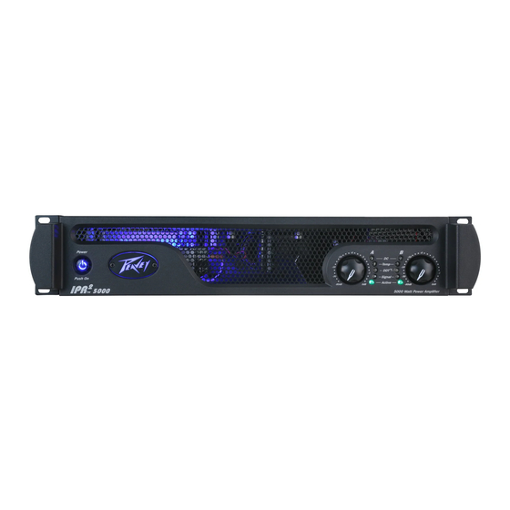
Page 7: Front Panel
Front Panel ™ IPR2 7500 ™ IPR2 5000 AC POWER SWITCH This button triggers the relay that provides power to the amplifier. This unique power switch will glow blue dimly. When turned on, it illuminates brightly. INDICATORS ™ ™ The IPR2 amplifiers feature five front-panel LED indicators per channel: ACTIVE, SIGNAL, DDT , TEMP and DC. - Page 8 Rear Panel ™ IPR2 7500 CHANNEL MODE SWITCH: HIGH PASS This position is used to activate the HIGH PASS filter for the corresponding channel. This filter will limit the frequencies sent to the associated amplifier channel to frequencies above 100 Hz. In situations where separate subwoofer cabinets are being used, this position would indicate connecting the mid-high frequency speaker cabinet to the channel associated with the HIGH PASS switch.
- Page 9 In the unlikely event of operating conditions that may potentially damage the amplifier, the circuit breaker may trip. After inspecting the cables and connections, the amplifier can be reset. If the circuit breaker trips a second time, contact the local Peavey authorized service center. AC POWER INLET: This is the receptacle for an IEC line cord, which provides AC power to the unit.
- Page 10 ENGLISH ™ IPR2 5000/7500 DSP Power Amplifier As the name implies, the IPR2 ™ 5000 and 7500 DSP all include advanced digital signal processing. The DSP was designed to be incredibly effective, yet extremely easy to use. Using unique and revolutionary advanced bass enhancement processes, the IPR2 DSP amplifiers dramatically improve the perceived level of bass in any system, using a fraction of the power that would be required with any other power amp.
- Page 11 AC POWER SWITCH This button triggers the relay that provides power to the amplifier. This unique power switch will glow blue (along with the Peavey logo) in standby mode, indicating AC power has been connected to the amplifier but the amplifier has not yet been turned on.
- Page 12 In the unlikely event of operating conditions that may potentially damage the amplifier, the circuit breaker may trip. After inspecting the cables and connections, the amplifier can be reset. If the circuit breaker trips a second time, contact the local Peavey authorized service center. AC POWER INLET: This is the receptacle for an IEC line cord, which provides AC power to the unit.
- Page 13 Navigation Overview Once the IPR screen appears, you can start adjusting the DSP processor. Pressing the encoder will bring you to the main menu. The encoder knob to the right of the display is used to navigate and control the DSP functions. The Channel A and B controls to the left of the display are also encoders but are dedicated to adjusting input gain for each channel.
- Page 14 To select an item from the Main Menu, rotate the encoder until the cursor marks the selection you want. Press the encoder to navigate to the Sub Menu adjustment screens for that processing function. When you enter a processing function Sub Menu, the cursor will appear in the upper left corner of the screen allowing you to scroll through Sub Menu screens.
- Page 15 Unlike the other function Sub Menus, the input mode does not change until you select “Save and Apply” and return to the Main Menu. Crossover Filters, Band-Pass Filters and Polarity Set: BP Filters Independently When you enter the “XOVER” Sub Menu, you are given three options for how the band-pass filters can be set.
- Page 16 Output Polarity Output Polarity The output polarity can be inverted on either channel. Select Normal or Invert in the polarity screen. If you create a crossover with 12dB per octave filters, the high frequency output would likely need to be inverted to maintain the proper phase relationship at the crossover frequency.
- Page 17 Horn EQ The Horn EQ provides a 6dB per octave high frequency boost that is sometimes required for high frequency horns. The frequency control sets the low frequency corner of the filter. To return to the Main Menu, select Discard and Exit or Save and Exit.
- Page 18 Saving Settings In the Memory Operation Sub Menu, select “Save Settings.” Select one of the four preset locations. Edit the name by rotating the cursor to select the character and pressing the encoder to step to the next position. Continue until complete.
- Page 19 ™ IPR2 7500 Specification Sheet Rated Watts 2ch x 2 ohms 4750 watts 20ms repetitive burst / 3750 watts 1% THD both channels driven @ 1kHz. Rated Watts 2ch x 4 ohms 2800 watts 20ms repetitive burst / 2450 watts 1% THD / 2020 watts 0.15% THD, both channels driven @ 1kHz. Rated Watts 2ch x 8 ohms 1550 watts 20ms repetitive burst / 1425 watts 1% THD / 1200 watts 0.15% THD, both channels driven @ 1kHz.
- Page 20 Warranty registration and information for U.S. customers available online at www.peavey.com/warranty or use the QR tag below Features and specifications subject to change without notice. Peavey Electronics Corporation 5022 Hartley Peavey Drive Meridian, MS 39305 (601) 483-5365 FAX (601) 486-1278 Logo referenced in Directive 2002/96/EC Annex IV (OJ(L)37/38,13.02.03 and defined in EN 50419: 2005...