Advertisement
Quick Links
Installation guide
Pressure switch
RT 5, RT 110, RT 112, RT 116, RT 117, RT 121, RT 200
Code no.
017xxxx
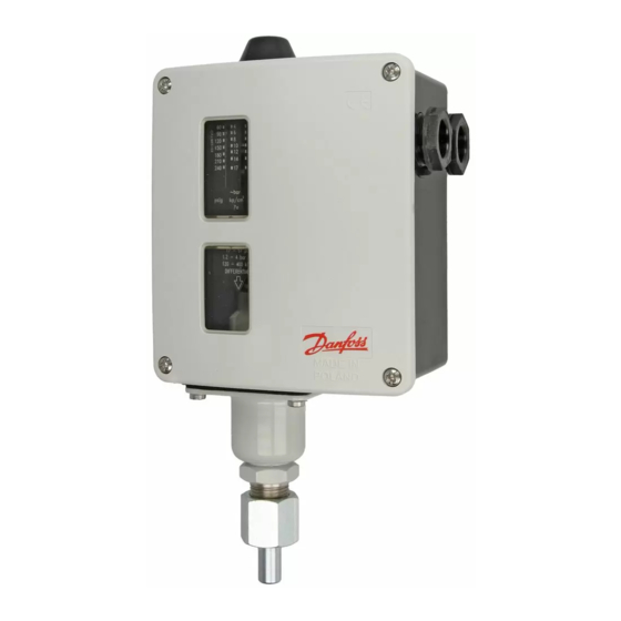
Fig. 1
Fig. 5
ENGLISH
Data
Pressure switch, types RT 5, RT 110,
RT 112, RT 117, RT 121, RT 200, RT 116
Max. test pressure
RT 110, RT 112, RT 121:
8 bar
RT 5, RT 116, RT 200:
25 bar
RT 117:
47 bar
Fitting
A set of Pg13.5 cable gland is attached to
the RT in a separate bag. To ensure IP66
(units with automatic reset) or IP54 (units
with external reset) grade of RT enclosure
it is necessary to assemble this gland as
shown in the fig. 2. If this gland is not used
with a cable, a metal blinding should be also
assembled.
Damp out strong pressure pulsations.
A damping coil, fig. 3 or fig. 4, will often be
sufficient.
Insert a water-filled tube loop as a
temperature lock (e.g. a 10 mm Cu tube) if at
high plant temperatures there is a risk that
the pressure connection of the control will
become heated to more than 100 °C.
Position the pressure control so that on
water plant it cannot be exposed to frost. It
can operate on an air cushion, for example.
© Danfoss | DCS (jmn) | 2015.11
Fig. 2
Fig. 6
Setting
The pressure controller is set by rotating the
knob (5), at the same time reading the main
scale (9). See fig. 1.
The differential is set by rotating the
differential adjusting nut (19) to the value
indicated by the use of the nomogram in
fig. 6. The maximum operating pressure is
thus the sum of the setting pressure and the
differential.
Example
It is desired to control the pressure in an
oilfired steam boiler by the use of an RT 116.
Maximum pressure 9 bar.
Minimum pressure 8.2 bar.
Differential 9 - 8.2 = 0.8 bar.
1. Connect the oil burner to terminals 1-2
of the pressure switch.
2. Set the pressure switch for 8.2 bar by
rotating the knob (5).
3. Set the differential adjusting nut (19) at
the figure 7 which is found by reading
the nomogram in fig. 6.
DANSK
Data
Pressostater type RT 5, RT 110, RT 112,
RT 117, RT 121, RT 200, RT 116
1 m Cu
/
- 20 UNF
7
16
Code no.
Code no.
060-333366
060-007166
Fig. 3
Fig. 4
Fig. 7
Max. prøvetryk
RT 110, RT 112, RT 121:
8 bar
RT 5, RT 116, RT 200:
25 bar
RT 117:
47 bar
Montering
Et sæt Pg13,5 kabelforskruning er vedlagt
produktet i en separat pose. For at sikre
kapslingsgrad IP66 (enheder med automatisk
reset) eller IP54 (enheder med ekstern DANSK
RESET) er det nødvendigt at montere denne
kabelforskruning som vist i fig. 3. Hvis denne
kabelforskruning ikke bruges sammen med
et kabel, bør der monteres en blindprop
(metal skive).
Dæmp kraftige trykpulsationer. Ofte er
dæmpesløjfe fig.3 eller fig. 4 tilstrækkelig.
Indskyd en vandfyldt rørsløjfe som
temperaturspærre, fx af10 mm Cu-rør, hvis
der i anlæg med høje temperaturer er risiko
for at pressostatens tryktiIslutning kan
opvarmes til over 100 °C.
Anbring pressostaten, så den ved vandanlæg
ikke udsættes for frost (lad den fx ar-bejde på
en luftpude).
Indstilling
Pressostaten indstilles efter. den funktion -
slutte eller bryde - som skal ske ved faldende
tryk (områdeindstilling).
Selve indstillingen udføres med hånd-
IC.PI.P10.C5.53 | 520B7012 | 1
Advertisement

Related Manuals for Danfoss RT 112


Summary of Contents for Danfoss RT 112
-
Page 1: Installation Guide
Installation guide Pressure switch RT 5, RT 110, RT 112, RT 116, RT 117, RT 121, RT 200 1 m Cu - 20 UNF Code no. Code no. Code no. 060-333366 060-007166 017xxxx Fig. 1 Fig. 2 Fig. 3 Fig. 4 Fig. - Page 2 Características (19) efter nomogrammet i figur 6. Højeste 1. Ölbrenner an die Klemmen 1-2 des Pres- Presostatos tipos RT 5, RT 110, RT 112, funktionstryk er således lig summen af sostats anschliessen. RT 117, RT 121, RT 200, RT 116 indstillingstryk og differens.