Table of Contents
Advertisement
Service
Manual
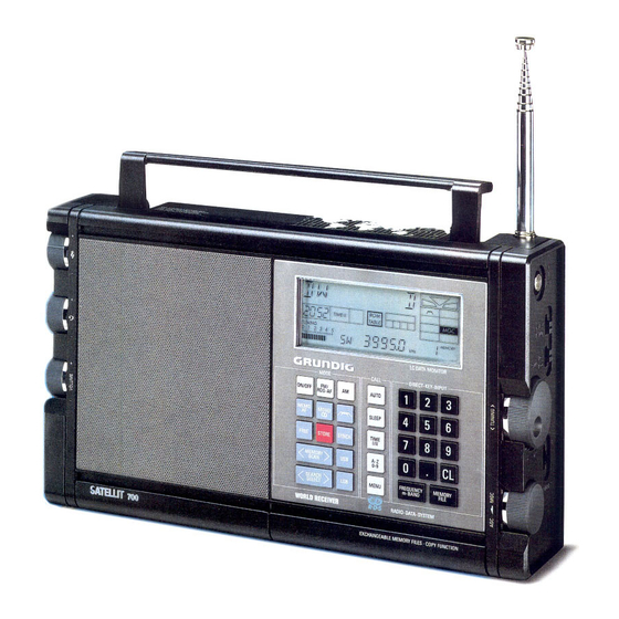
Satellit 700 (9.15055-8151) / Satellit 700 USA (9.15055-7151) / Satellit 700 GB (9.15055-6251) / Satellit 700 Italia (9.15055-6151)
D
Inhaltsverzeichnis
Technische Daten ........................................................................... 2
Sicherheitshinweise ............................................................... 3-5
Sicherheitshinweise zu Lithiumbatterien .................................. 5
Chip-Technik ......................................................................... 6-7
Behandlung von MOS-Bauteilen ........................................... 7-8
Ausbauhinweise ......................................................................... 9-10
Spannungsversorgung ........................................................... 11
Autom. Steuerung eines Cassettengerätes ............................ 12
Befestigen des Gerätes .......................................................... 12
Memofiles ............................................................................... 12
Lautsprecher-Buchse ............................................................. 12
Synchrondetektor ................................................................... 13
RDS-Testmode ....................................................................... 13
Testmode ...................................................................................... 14
Abgleich ................................................................................... 15-18
Schaltbilder:
HF-Platte ........................................................................... 23-26
Prozessorplatte .................................................................. 27-30
Bedienplatte ....................................................................... 35-37
NF- und Potiplatte .............................................................. 38-40
Druckplattenabbildungen:
HF-Platte ........................................................................... 19-22
Prozessorplatte .................................................................. 31-32
Bedienplatte ....................................................................... 33-34
NF- und Potiplatte .............................................................. 41-42
Schaltbildhinweise ........................................................................ 43
Ersatzteilliste ............................................................................ 44-52
+
-
+
-
+
-
700
SERVICE MANUAL
AUTO
ROM
MEMOFILE
TIME II
SLEEP
TABLE
1 2 3
TUNING
0 1 2 3 4 5
BA TT./ACCU
MODE
CALL
FM/
ON/OFF
AM
AUTO
RDS-AF
MEMO
MONO
SLEEP
AF
TIME
FREE
STORE
SYNCH
I/II
A-Z
MEMORY
USB
SCAN
0-9
SEARCH
LSB
MENU
SELECT
WORLD RECEIVER
R•D•S
EXCHANGEABLE MEMORY FILES COPY FUNCTION
GB
Contents
Seite
Specification .................................................................................... 2
General Notes:
Safety Requirements ............................................................. 3-5
Safety Cautions for Lithium Batteries ....................................... 5
Chip Technology .................................................................... 6-7
Handling of MOS Chip Components ..................................... 7-8
Disassembly Instructions ........................................................... 9-10
Notes for the Satellit 700:
Power Supply ......................................................................... 11
Autom. Control of a Cassette Recorder .................................. 12
Securing the Unit .................................................................... 12
Memofiles ............................................................................... 12
Loudspeaker Socket ............................................................... 12
Synchronous Demodulator ..................................................... 13
RDS-Testmode ....................................................................... 13
Testmode ...................................................................................... 14
Alignment ................................................................................. 15-18
Circuit Diagrams:
RF Board ........................................................................... 23-26
Processor Board ................................................................ 27-30
Operating Board ................................................................ 35-37
AF- and Potentiometer Board ............................................ 38-40
Illustration of Printed Boards:
RF Board ........................................................................... 19-22
Processor Board ................................................................ 31-32
Operating Board ................................................................ 33-34
AF- and Potentiometer Board ............................................ 41-42
Notes for the Circuit Diagram ........................................................ 43
List of Spare Parts ................................................................... 44-52
Printed in Germany
VK 225 1291
Satellit 700
SYNCH
LSB
USB
EXT
LOC
MONO
4
STEREO
MGC
R D S
ACCU
MHz
MEMORY
m
kHz
LC DATA MONITOR
DIRECT-KEY-INPUT
1
2
3
4
5
6
7
8
9
0
CL
FREQUENCY
MEMORY
m-BAND
FILE
RADIO-DATA-SYSTEM
Service Manual Sach-Nr. 72010-719.55
Service Manual Part No.
*
Page
72010-719.55
Advertisement
Table of Contents

Related Manuals for Grundig Satellit 700


Summary of Contents for Grundig Satellit 700
-
Page 1: Table Of Contents
SERVICE MANUAL Service Manual Satellit 700 Satellit 700 (9.15055-8151) / Satellit 700 USA (9.15055-7151) / Satellit 700 GB (9.15055-6251) / Satellit 700 Italia (9.15055-6151) SYNCH MONO AUTO MEMOFILE TIME II SLEEP TABLE 1 2 3 STEREO R D S ACCU... -
Page 2: Technische Daten
Technische Daten / Specification Satellit 700 Technische Daten Specification Spannungsversorgung Power supply requirement - Durch Batterien: - From batteries: 4 x 1,5 V-Monozellen (IEC LR20) oder 4 x handelübliche 4 Ah-Akkus 4 x 1.5 V"HP 2" (IEC LR20) or 4 commercially available 4 Ah in gleicher Größe (IEC KR 35/62). -
Page 3: Allgemeine Hinweise
Satellit 700 Allgemeine Hinweise / General Notes Allgemeine Hinweise General Notes Sicherheitsvorschriften/Safety requirements/Prescrizioni de sicurezza/Prescriptions de sécurité/ Prescripciones de seguridad Achtung: Bei Eingriffen ins Gerät sind die Sicherheitsvor- Attention: Priere d`observer les prescriptions de securite VDE 701 (concernant les reparations) et VDE 0860 / IEC 65 schriften nach VDE 701 (reparaturbezogen) bzw. - Page 4 Allgemeine Hinweise / General Notes Satellit 700 Prescriptions de securite Recommandations pour la maintenance Suite aux travaux de maintenance sur les appareils de la classe II, il • Utiliser exclusivement des piéces de rechange d’origine. Les convient de mesurer la résistance d’isolement et le courant de fuite sur composants et ensembles de composants signalés par le symbole...
-
Page 5: Sicherheitshinweise Zu Lithiumbatterien
Satellit 700 Allgemeine Hinweise / General Notes ü U.S.& Canada Safety Instructions The lightning flash with arrowhead symbol, within an equilate- • Power Sources - The appliance should be connected to a ral triangle, is intended to alert the user to the presence of power supply only of the type given above or as marked on the uninsulated "dangerous voltage", within the product´s enclo-... -
Page 6: Chip-Technik
Allgemeine Hinweise / General Notes Satellit 700 CHIP Technik CHIP Technology Aus- und Einlöten von CHIP-Bauteilen Soldering and unsoldering of CHIP components - Verwenden Sie nur einen Niedervoltlötkolben mit Temperatur- - Use only low-voltage soldering irons with temperature control. - Permissible soldering temperatures are approx. 240 °C up to regelung. - Page 7 Satellit 700 Allgemeine Hinweise / General Notes Fixierpunkt Técnica de CHIP´s Fixing point Punto di fissaggio Lötzinn Point de soudure Solder Soldaje y desoldaje de CHIP´s Punto de fijación Stagno - Emplear sólo un soldador de bajo voltaje con regulación de Soudure temperatura.
- Page 8 Allgemeine Hinweise / General Notes Satellit 700 Impiego dei componenti MOS 3. Maneggiare i componenti MOS toccandone solo l´involucro e mai i I circuiti in tecnica MOS necessitano di una particolare attenzione per evitare le scariche elettrostatiche. piedini. 4. Controlli e lavorazioni devono avvenire soltanto su apparecchi con Tutti i materiali sintetici ad alto potere isolante possono caricar si messa a terra.
-
Page 9: Ausbauhinweise
Satellit 700 Ausbauhinweise / Disassembly Instructions Ausbauhinweise Disassembly Instructions GRUNDIG Service-Technik... - Page 10 Ausbauhinweise / Disassembly Instructions Satellit 700 Rückwand Rear Panel. - 4 Schrauben A herausschrauben. - Unscrew 4 screws A. - Rückwand an der Bodenseite anheben und vorsichtig aufklappen. - Lift the rear panel at the bottom side and remove it carefully.
-
Page 11: Hinweise Zum Satellit 700
Satellit 700 Hinweise zum Satellit 700 / Notes for the Satellit 700 Hinweise zum Satellit 700 Notes for the Satellit 700 Spannungsversorgung Power Supply Batterie- bzw. Accu-Betrieb Battery or Accumulator Operation Mit 4 Monozellen IEC LR 20 (Alkali-Mangan-Batterien) bzw. handel- With 4 "HP2"... -
Page 12: Befestigen Des Gerätes
Hinweise zum Satellit 700 / Notes for the Satellit 700 Satellit 700 Automatic Control of a Automatische Steuerung Cassette Recorder eines Cassettengerätes Steuerlogik/Control logic: Schaltstellung bei SAT 700 With the Satellit 700 it is possible to Der Satellit 700 kann ein Cassetten-... -
Page 13: Synchrondetektor
Satellit 700 Hinweise zum Satellit 700 / Notes for the Satellit 700 Sender-Träger Carrier Synchrondetektor Unteres Seitenband Oberes Seitenband Unteres Seitenband des Synchronous Demodulator danebenliegenden Senders Lower sideband Upper sideband Reicht die Bandbreiteneinstellung Lower sideband of ( LSB ) ( USB ) adjacent station "schmal"... -
Page 14: Testmode
Testmode Satellit 700 Testmode Testmode Aktivieren des Testmodes Activation of the Testmode - Gerät ausschalten. - Switch off the unit. - Eingabe des Testcodes 050251. - Enter the testcode 050251. - Drücken der Taste STORE. - Push the button STORE. -
Page 15: Abgleich
Satellit 700 Abgleich / Alignment Abgleich Alignment Bei Batteriespannung U = 6 V. At batterie voltage U = 6 V. Bedieneinheit Operating Unit Uhrfrequenz Clock frequency Voreinstellungen: keine Presettings: none Einspeisung: keine Feeding: none Messung: Frequenzzähler mit Tastkopf lose an Meßpunkt... -
Page 16: Abgleich
Abgleich / Alignment Satellit 700 SW-Vorkreise SW-RF circuit Voreinstellungen: Antennenschalter INT; Presettings: SW; Aerial switch to INT; Distant/Local switch to DX; Empfindlichkeitsschalter auf DX; Teleskopantenne ablöten. unsolder the telescopic aerial. Einspeisung: Wobbler über 15 pF an Meßpunktt Feeding: Sweep generator with 15 pF to testpoint Messung: Oszilloskop an Meßpunkt... - Page 17 Satellit 700 Abgleich / Alignment Satellit 700 Abgleich / Alignment Suchlauf Station search Voreinstellungen: FM; Antennenschalter auf EXT. Presettings: FM; Aerial switch to EXT. Einspeisung: Meßsender an Antennenbuchse; Feeding: Test generator to aerial socket; = 50 Hz,100 µV, ∆f = 50 kHz;...
- Page 18 Druckplattenabbildungen HF-Platte / Illustration of RF Board Satellit 700 Druckplattenabbildungen HF-Platte / Illustration of RF Board Satellit 700 Bauteil Bauteil CR 0259 CR 0822 CR 0261 CR 0823 CR 0262 CR 0824 CR 0301 CR 0825 CR 0302 CR 0826...
-
Page 19: Prozessorplatte
Satellit 700 Druckplattenabbildungen HF-Platte / Illustration of RF Board Satellit 700 Druckplattenabbildungen HF-Platte / Illustration of RF Board Ext. Prozessorplatte Processor Board CLARIFY NF-Platte AF-Board GRUNDIG Service-Technik GRUNDIG Service-Technik... - Page 20 Schaltbild HF-Platte / Circuit Diagram of RF Board Satellit 700 Schaltbild HF-Platte / Circuit Diagram of RF Board Satellit 700 GRUNDIG Service-Technik GRUNDIG Service-Technik...
- Page 21 Satellit 700 Schaltbild HF-Platte / Circuit Diagram of RF Board Satellit 700 Schaltbild HF-Platte / Circuit Diagram of RF Board GRUNDIG Service-Technik GRUNDIG Service-Technik...
- Page 22 Schaltbild Prozessorplatte / Circuit Diagram of Processor Board Satellit 700 Schaltbild Prozessorplatte / Circuit Diagram of Processor Board Satellit 700 GRUNDIG Service-Technik GRUNDIG Service-Technik...
- Page 23 Satellit 700 Schaltbild Prozessorplatte / Circuit Diagram of Processor Board Satellit 700 Schaltbild Prozessorplatte / Circuit Diagram of Processor Board GRUNDIG Service-Technik GRUNDIG Service-Technik...
- Page 24 Druckplattenabbildungen HF-Platte / Illustration of RF Board Satellit 700 Druckplattenabbildungen HF-Platte / Illustration of RF Board Satellit 700 Bauteil Bauteil Bauteil Bauteil Bauteil Bauteil CC 1102 102 CC 1135 CR 1125 CR 1154 CR 1182 101 CT 1108 110 CC 1103 100...
- Page 25 Satellit 700 Druckplattenabbildungen HF-Platte / Illustration of RF Board Satellit 700 Druckplattenabbildungen HF-Platte / Illustration of RF Board Bauteil Bauteil Bauteil CC 0011 217 CR 0007 202 CR 0025 151 CC 0012 213 CR 0008 197 CR 0026 152 CC 0013 218...
- Page 26 Schaltbild Bedienplatte / Circuit Diagram of Operating Board Satellit 700 Schaltbild Bedienplatte / Circuit Diagram of Operating Board Satellit 700 GRUNDIG Service-Technik GRUNDIG Service-Technik...
- Page 27 Satellit 700 Schaltbild Bedienplatte / Circuit Diagram of Operating Board GRUNDIG Service-Technik...
- Page 28 Schaltbild NF- und Potiplatte / Circuit Diagram of AF and Potentiometer Board Satellit 700 GRUNDIG Service-Technik...
- Page 29 Satellit 700 Schaltbild NF- und Potiplatte / Circuit Diagram of AF and Potentiometer Board Satellit 700 Schaltbild NF- und Potiplatte / Circuit Diagram of AF and Potentiometer Board GRUNDIG Service-Technik GRUNDIG Service-Technik...
- Page 30 Druckplattenabbildungen HF-Platte / Illustration of RF Board Satellit 700 Druckplattenabbildungen HF-Platte / Illustration of RF Board Satellit 700 Line Out HF-Platte BU5 RF Board BU5 LK/RK ext. ext. DC R756 R751 R748 R656 R651 R648 LOCK Bauteil Bauteil Bauteil Bauteil...
- Page 31 Satellit 700 Schaltbildhinweise / Notes for the Circuit Diagram GRUNDIG Service-Technik...
-
Page 32: Ersatzteilliste
Satellit 700 Ersatzteilliste / List of Spare Parts Ersatzteilliste List of spare parts 3 / 91 SATELLIT 700 SACH-NR. / PART NO.: 9.15055-8151 G.RB 6051 P 9.15055-6251 G.RB 6051 GB P 9.15055-7151 G.RB 6051 UB P 9.15055-6151 G.RB 6051 IB P POS. -
Page 33: List Of Spare Parts
Satellit 700 Ersatzteilliste / List of Spare Parts POS. SACHNUMMER BEZEICHNUNG POS. SACHNUMMER BEZEICHNUNG DESCRIPTION POS. PART NUMBER POS. PART NUMBER DESCRIPTION CC 216 8672-267-187 KEFQ 1206 0,1 UF 10% CC 217 8672-267-187 KEFQ 1206 0,1 UF 10% CC 218... - Page 34 Satellit 700 Ersatzteilliste / List of Spare Parts POS. SACHNUMMER BEZEICHNUNG POS. SACHNUMMER BEZEICHNUNG DESCRIPTION POS. PART NUMBER POS. PART NUMBER DESCRIPTION CC 439 8672-267-179 KEFQ 1206 0,047UF 10% CC 827 8672-167-250 KEFQ 0805 2200PF 10% CC 441 8672-267-179 KEFQ 1206...
- Page 35 Satellit 700 Ersatzteilliste / List of Spare Parts POS. SACHNUMMER BEZEICHNUNG POS. SACHNUMMER BEZEICHNUNG DESCRIPTION POS. PART NUMBER POS. PART NUMBER DESCRIPTION CR 13 8706-100-097 R-CHIP 0805 10 KOHM 5% CR 213 8706-100-121 R-CHIP 0805 100 KOHM 5% CR 14...
- Page 36 Satellit 700 Ersatzteilliste / List of Spare Parts POS. SACHNUMMER BEZEICHNUNG POS. SACHNUMMER BEZEICHNUNG DESCRIPTION POS. PART NUMBER POS. PART NUMBER DESCRIPTION CR 403 8706-100-061 R-CHIP 0805 330 OHM 5% CR 606 8706-100-089 R-CHIP 0805 4,7 KOHM 5% CR 404...
- Page 37 Satellit 700 Ersatzteilliste / List of Spare Parts POS. SACHNUMMER BEZEICHNUNG POS. SACHNUMMER BEZEICHNUNG DESCRIPTION POS. PART NUMBER POS. PART NUMBER DESCRIPTION CR 761 8706-100-131 R-CHIP 0805 270 KOHM 5% CR 911 8706-100-097 R-CHIP 0805 10 KOHM 5% CR 762...
- Page 38 Satellit 700 Ersatzteilliste / List of Spare Parts POS. SACHNUMMER BEZEICHNUNG POS. SACHNUMMER BEZEICHNUNG DESCRIPTION POS. PART NUMBER POS. PART NUMBER DESCRIPTION CR 1151 8706-100-097 R-CHIP 0805 10 KOHM 5% CT 402 8301-130-543 SMD-TRANS.BF 543 E 7810 CR 1152 8706-100-097...
- Page 39 Satellit 700 Ersatzteilliste / List of Spare Parts POS. SACHNUMMER BEZEICHNUNG POS. SACHNUMMER BEZEICHNUNG DESCRIPTION POS. PART NUMBER POS. PART NUMBER DESCRIPTION 19203-121.14 KERAMIK-FILTER-SATZ 19203-121.14 KERAMIK-FILTER-SATZ 19202-701.97 SPULE 10X10 8382-251-497 QUARZFILTER 54,5 MHZ D 11 8309-215-043 DIODE 1 N 4151 PHI/TFK/ 07202-635.97...
-
Page 40: Änderungen Vorbehalten Subject To Alteration
Satellit 700 Ersatzteilliste / List of Spare Parts POS. SACHNUMMER BEZEICHNUNG POS. SACHNUMMER BEZEICHNUNG DESCRIPTION DESCRIPTION POS. PART NUMBER POS. PART NUMBER R 812 8792-002-164 ESTR.S6 100 KOHM LIN LA 1 8316-113-109 LAMPE T1 5V 60MA 683-1 R 813 19703-213.00 POTENTIOMETER /HF PL.