Table of Contents
Advertisement
Your new tool has been engineered and manufactured to WEN's highest standards for dependability,
ease of operation, and operator safety. When properly cared for, this product will supply you years
of rugged, trouble-free performance. Pay close attention to the rules for safe operation, warnings,
and cautions. If you use your tool properly and for intended purpose, you will enjoy years of safe,
reliable service.
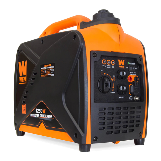
1250W INVERTER
GENERATOR
IMPORTANT:
NEED HELP? CONTACT US!
Have product questions? Need technical support?
Please feel free to contact us at:
800-232-1195
techsupport@wenproducts.com
WENPRODUCTS.COM
Model #56125i
bit.ly/WENvideo
(M-F 8AM-5PM CST)
Advertisement
Table of Contents

Related Manuals for Wen 56125i


Summary of Contents for Wen 56125i
- Page 1 IMPORTANT: Your new tool has been engineered and manufactured to WEN’s highest standards for dependability, ease of operation, and operator safety. When properly cared for, this product will supply you years of rugged, trouble-free performance. Pay close attention to the rules for safe operation, warnings, and cautions.
-
Page 2: Table Of Contents
TABLE OF CONTENTS Generator Identification Service Record Introduction Safety Information Generator Components Generator Preparation Starting the Generator Stopping the Generator Subsequent Starting of the Generator Using the Generator Maintenance & Care Specifications Troubleshooting Storage & Transport Exploded View and Parts List Wiring Diagram Warranty Statement... -
Page 3: Generator Identification
GENERATOR IDENTIFICATION If assistance for information or service is required, please contact the Customer Service Help Line by calling 800-232-1195; customer will be asked to provide generator information when calling. Refer to the illustration below for the location of the serial number. Record generator information in the spaces provided below. -
Page 4: Introduction
Every effort has been made to ensure the accuracy of the information in this manu- al. WEN reserves the right to change this product, manual and specifications at any time without prior notice. Please keep this manual available to all users during the entire life of the generator. - Page 5 SAFETY INFORMATION For any questions regarding the hazard and safety notices listed in this manual or on the product, please call (800) 232-1195 M-F 8-5 CST before using the generator. DANGER: CARBON MONOXIDE Using a generator indoors CAN KILL YOU IN MINUTES. Generator exhaust contains carbon monox- ide (CO).
- Page 6 150 F (65 SAVE THESE INSTRUCTIONS – This manual contains important instructions for the WEN generator that should be followed during installation and maintenance of the generator. Generators vibrate in normal use. During and after the use of the generator, inspect both the generator as well as extension and power supply cords for damage resulting from vibration.
-
Page 7: Generator Components
GENERATOR COMPONENTS Use the illustrations below to become familiar with the locations and functions of the various components and controls of this generator. Pressure Relief Gas Cap Valve Spark Plug Eco-Mode Indicator Lights 3-in-1 Switch Recoil Starter 120V Duplex Receptacle USB Charger Parallel Connection Ports Grounding Nut... -
Page 8: Generator Preparation
GENERATOR PREPARATION USING THE GENERATOR FOR THE FIRST TIME CAUTION: The following section describes the necessary steps to prepare the generator for use. If after reading this section, you are unsure about how to perform any of the steps please call (800) 232-1195 M-F 8-5 CST for customer service. - Page 9 GENERATOR PREPARATION WARNING: This generator may emit highly flammable and explosive gasoline vapors, which can cause severe burns or even death if ignited. A nearby open flame can lead to explosion even if not directly in contact with gasoline. Step 2 - ADD GASOLINE IMPORTANT: •...
-
Page 10: Starting The Generator
STARTING THE GENERATOR Before starting the generator, make sure you have read and performed the steps in the “Generator Preparation” section of this manual. If you are unsure about how to perform any of the steps in this manual please call (800) 232-1195 M-F 8-5 CST for customer service. - Page 11 STARTING THE GENERATOR STARTING THE ENGINE (FIG. 4) To start the generator, perform the following steps: 1. Unplug all electrical devices from the generator before starting. Otherwise it can be difficult to start the engine. 2. To maximize safety, make sure the generator is properly grounded (Refer to “Ground the Generator”).
-
Page 12: Stopping The Generator
STOPPING THE GENERATOR TO STOP THE GENERATOR 1. Turn off all electrical devices prior to unplugging them from the generator. Unplugging running devices can cause damage to the generator. After turning the devices off, unplug them all from the generator. 2. -
Page 13: Using The Generator
The surge wattage ability of the generator covers this extra power requirement. Item Rated (Running) Wattage Surge Wattage 56125i 1000 1250 Fig. 5 - Generator Wattage The total running wattage requirement of the electrical devices connected to the generator should not exceed the rated wattage of the generator itself. - Page 14 USING THE GENERATOR If the electrical specifications are not available for your electronic devices, estimate the watts requirement of the device by using the chart in Figure 6. When the rated wattage requirement of each electrical device has been determined, add these numbers to find the total rated wattage needed.
-
Page 15: Maintenance & Care
USING THE GENERATOR CAUTION: Do not connect 50Hz loads to the generator. SOME NOTES ABOUT POWER CORDS Long or thin cords can drain the power provided to an electrical device by the generator. When using such cords, allow for a slightly higher rated wattage requirement by the electrical device. See Figure 7 for recommended cords based on the power requirement of the electrical device. - Page 16 MAINTENANCE & CARE CLEANING THE GENERATOR Never clean the generator when it is running! Never clean with a bucket of water or a hose. Water can get inside the working parts of the generator and cause corrosion or a short circuit. Always try to use the generator in a cool, dry place.
- Page 17 MAINTENANCE & CARE CHANGING/ADDING OIL Change the oil according to the Recommended Maintenance Schedule in Figure 9 by removing the side panel of the generator opposite of the recoil starter. Change the oil when the engine is warm. This will allow for complete drainage.
- Page 18 MAINTENANCE & CARE SPARK PLUG MAINTENANCE (Fig. 11) The spark plug is important for proper engine operation. A good spark plug should be intact, free of deposits, and properly gapped. Refer to Recommended Maintenance Schedule in Figure 8. To inspect the spark plug: 1.
-
Page 19: Specifications
MAINTENANCE & CARE DRAINING THE CARBURETOR After each use, open up the carburetor drain with a screwdriver and drain out any gasoline that has built up inside. Once the fuel has drained, close the drain back up with the same screwdriver. It is best to do this after every use and required before storing the generator for long periods of time. -
Page 20: Troubleshooting
TROUBLESHOOTING IMPORTANT: If trouble persists, please call our customer help line at (800) 232-1195 M-F 8-5 Central Time. Problem Cause Solution Engine switch is in the OFF position Set the engine switch to the CHOKE position Engine is filled with contaminated Change the fuel in the tank or old fuel Not enough oil in crankcase... -
Page 21: Exploded View And Parts List
EXPLODED VIEW AND PARTS LIST Fig. 2 Crankcase No. Part Number Description 56125-0201 Crankcase Subassembly 56125-0202 Stud Fig. 1 - Cylinder 56125-0203 Stud No. Part Number Description 56125-0204 Crankcase Cover 56125-0101 Cylinder Head Cover Bolts 56125-0205 Gear 56125-0102 Cylinder Head Cover 56125-0206 Gear Shaft 56125-0103... - Page 22 Fig. 5 - Recoil Starter No. Part Number Description Fig. 4 - Camshaft 56125-0501 Intake Tube No. Part Number Description 56125-0502 Collar 56125-0401 Camshaft Gear 56125-0503 Shroud 56125-0402 Camshaft Rod 56125-0504 Shourd Mounting Bolts 56125-0403 Lower Rocker 56125-0505 Recoil Assembly 56125-0404 Lower Rocker 56125-0506...
- Page 23 Fig. 8 - Muffler Assembly Fig. 7 - Fuel Tank No. Part Number Description No. Part Number Description 56125-0801 Muffler Shroud 56125-0701 Gas Cap 56125-0802 Muffler Shroud 56125-0702 Gas Tank Nozzle Sleeve 56125-0803 Collar 56125-0703 Gas Tank 56125-0804 Shroud Bolts 56125-0704 Gas Tank Shock Absorber 56125-0805...
- Page 24 Fig. 10 - Casing Fig. 10 - Casing No. Part Number Description No. Part Number Description 10-1 56125-1001 Left Panel 10-16 56125-1016 Bolts for Feet 10-2 56125-1002 Panel Screws 10-17 56125-1017 Fuel Cock 10-3 56125-1003 Right Panel 10-18 56125-1018 Fuel Cock Bolt 10-4 56125-1004 Panel Screws...
- Page 25 Fig. 11 - Panel Assembly Fig. 11 - Panel Assembly Fig. 11 - Panel Assembly No. Part Number Description No. Part Number Description 11-1 56125-1101 Status Display 11-17 56125-1117 Choke Line 11-2 56125-1102 LED Indicators 11-18 56125-1118 Screw 11-3 56125-1103 120V Socket Receptacles 11-19 56125-1119...
-
Page 26: Wiring Diagram
WIRING DIAGRAM... -
Page 27: Warranty Statement
WEN® will repair or replace, at its discretion, any part that is proven to be defective in materials or workman- ship under normal use during the two (2) years warranty period. Warranty repairs or replacements will be made without charge for parts or labor. - Page 28 THANKS FOR REMEMBERING...