Table of Contents
Advertisement
Advertisement
Table of Contents
Troubleshooting

Related Manuals for Monarch NICE7000


Summary of Contents for Monarch NICE7000
-
Page 2: Preface
3. It supports a maximum of 56 floors and is widely applied to elevators used in the residence, office buildings, shopping centers, and hospitals. This manual describes the correct use of the NICE7000, including product features, safety information and precautions, installation, parameter setting, commissioning, and maintenance &... - Page 3 Notes • The drawings in the manual are sometimes shown without covers or protective guards. Remember to install the covers or protective guards as specified first, and then perform operations in accordance with the instructions. • The drawings in the manual are shown for description only and may not match the product you purchased.
- Page 4 NICE7000 User Manual Introduction Introduction 1. Product overview The NICE7000 integrates functions of the elevator controller and high-performance vector control AC drive. With the controller as the core, the elevator drive control system is constructed. 2. Product features The NICE7000 has the following major features: •...
-
Page 5: Introduction
Built-in real-time clock, which provides time-based services, facilitating intelligent floor service management Detailed fault records Flexible modular optional parts 3. Function list of the NICE7000 Common Running Functions In automatic running or attendant state, this function enables the elevator Full collective to respond both car calls and hall calls. - Page 6 NICE7000 User Manual Introduction If the door lock is not applied after the elevator performs door close for a Repeat door close certain time, the elevator automatically opens the door and then closes the door again. When the main and auxiliary operation boxes are configured, they can...
- Page 7 Introduction NICE7000 User Manual If the hall I/O terminals are not sufficient, more terminals can be provided Hall I/O extension function by using an HCB-B board. If the car I/O terminals are not sufficient, more terminals can be provided Car I/O extension function by using an HCB-B board.
- Page 8 NICE7000 User Manual Introduction The system automatically records detailed information of faults, which Fault data recording helps improve the efficiency of maintenance and repair. Inspection-related Functions Simple maintenance The 3-button keypad on the MCB provides the functions such as commissioning the running floors and door open/close.
- Page 9 Introduction NICE7000 User Manual Fire Emergency and Security Functions Returning to After receiving a fire emergency signal, the elevator does not respond to base floor at fire any call but directly runs to the fire emergency floor and waits. emergency...
- Page 10 The NICE7000 system supports not only three-phase 380 VAC but also Independent working single-phase 220 VAC to meet different applications of the power supply...
- Page 11 Introduction NICE7000 User Manual When the elevator is full-loaded, a full-load indication is displayed on the Full-load indication HCBs and the elevator directly runs to the desired floors. Interface for The system provides an interface for intelligent residential management intelligent residential...
-
Page 12: Table Of Contents
3.7 Selection of Braking Components ................. 59 3.8 Selection of Peripheral Electrical Devices ..............61 3.9 Electrical Wiring Diagram of the NICE7000 Control System ......... 63 3.10 Installation of Shaft Position Signals ................63 Chapter 4 Use of the Commissioning Tools ............70 4.1 Use of the Onboard Keypad .................. -
Page 13: Table Of Contents
5.3 Riding Comfort....................... 83 5.4 Password Setting......................87 5.5 System Functions ......................88 Chapter 6 Function Code Table ................. 102 6.1 Function Code Description ..................102 6.2 Function Code Groups ....................102 6.3 Function Code Table ....................103 Chapter 7 Description of Function Codes............134 Group F0: Basic Parameters ..................... -
Page 14: Table Of Contents
8.2 Description of Fault Levels ..................205 8.3 Fault Information and Troubleshooting ................ 207 Chapter 9 EMC ....................224 9.1 Definition of Terms ....................... 224 9.2 Introduction to EMC Standard ..................224 9.3 Selection of Peripheral EMC Devices................225 9.4 Shielded Cable ......................228 9.5 Solutions to Common EMC Interference Problems ............. - Page 16 Safety Information and Precautions...
- Page 17 The equipment is allowed to be operated by electrical engineers that are qualified by the factory or agent and have received processional training. Monarch will assume no liability or responsibility for any injury or loss caused by improper operation.
-
Page 18: Chapter 1 Safety Information And Precautions
NICE7000 User Manual 1 Safety Information and Precautions Use Stage Safety Grade Precautions • Wiring must be performed only by qualified personnel under instructions described in this manual. Failure to comply may result in unexpected accidents. • A circuit breaker must be used to isolate the power supply and the controller. -
Page 19: General Precautions
1 Safety Information and Precautions NICE7000 User Manual Use Stage Safety Grade Precautions • Check that the following requirements are met: - The voltage class of the power supply is consistent with the rated voltage class of the controller. - The input terminals (R, S, T) and output terminals (U, V, W) are properly connected. - Page 20 NICE7000 User Manual 1 Safety Information and Precautions controller. You can select a specialized RCD with the function of suppressing high harmonics or a general-purpose RCD with relatively large residual current. 2. Motor insulation test Perform the insulation test when the motor is used for the first time, or when it is reused after being stored for a long time, or in a regular check-up, in order to prevent the poor insulation of motor windings from damaging the controller.
- Page 21 9. Altitude and de-rating In places where the altitude is above 1000 m and the cooling effect reduces due to thin air, it is necessary to de-rate the controller. Contact Monarch for technical support. 10. Special usage If wiring that is not described in this manual, such as common DC bus is applied, contact the agent or Monarch for technical support.
- Page 22 NICE7000 User Manual 1 Safety Information and Precautions 12. Adaptable motor The controller is adaptable to squirrel-cage asynchronous motor or AC PMSM. Select a proper controller according to motor nameplate. The default parameters configured inside the controller are squirrel-cage asynchronous motor parameters.
- Page 23 1 Safety Information and Precautions NICE7000 User Manual - 22 -...
- Page 24 Product Information...
- Page 25 NICE7000 User Manual Chapter 2 Product Information 2.1 System Configuration of the NICE7000 The NICE7000 series integrated elevator control system mainly includes the integrated elevator controller, car top board (MCTC-CTB), hall call board (MCTC-HCB), and car call board (MCTC-CCB). The following figure shows the system components.
-
Page 26: Chapter 2 Product Information
S/N: Suzhou MONARCH Control Technology Co.Ltd The NICE7000 can drive both the AC asynchronous motor and PMSM. When encoder is used, select a PG card matching the encoder type. The structure in the controller model indicates the degree to which the PCB is enclosed by the shell. - Page 27 2 Product Information NICE7000 User Manual Figure 2-4 NICE7000 structures NICE-LQX-4015-A0 NICE-LQX-4015-B0 NICE-LQX-4015-C0 2.3 Models Table 2-1 NICE7000 models Power Input Current Output Current Motor Power Controller Model Capacity (kVA) (kW) Three-phase 220 V, range: -15% to 20% NICE-LQX-2002-A/B/C0 11.0 NICE-LQX-2003-A/B/C0 17.0...
-
Page 28: Models
NICE7000 User Manual 2 Product Information Power Input Current Output Current Motor Power Controller Model Capacity (kVA) (kW) 220-NICE-LQX-4022-A/B/C0 10.6 42.6 27.7 220-NICE-LQX-4030-A/B/C0 13.1 52.6 34.6 Three-phase 380 V, range: -15% to 20% NICE-LQX-4002-A/B/C0 NICE-LQX-4003-A/B/C0 10.5 NICE-LQX-4005-A/B/C0 14.8 13.0 11.0 NICE-LQX-4007-A/B/C0 20.5... -
Page 29: Technical Specifications
2 Product Information NICE7000 User Manual 2.4 Technical Specifications Table 2-2 Technical specifications of the NICE7000 Specification Item Maximum frequency 99 Hz 2–16 kHz, adjusted automatically based on the load Carrier frequency features • Sensorless vector control (SVC) • Closed-loop vector control (CLVC) Motor control mode •... - Page 30 NICE7000 User Manual 2 Product Information Specification Item Security check of Security check of peripheral devices, such as grounding peripheral devices and short circuit, after power-on Basic after power-on specifications Monitoring the state of feedback signals to ensure that the...
-
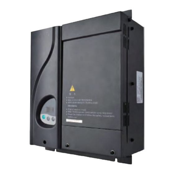
Page 31: Physical Appearance And Mounting Dimensions
2.5 Physical Appearance and Mounting Dimensions The following figure shows the physical appearance and mounting dimensions of the NICE7000. Figure 2-5 Physical appearance and mounting dimensions of the NICE7000 2.2 kW < P ≤ 30 kW 30 kW < P ≤ 160 kW Table 2-3 Mounting dimensions of the NICE7000 Φ... -
Page 32: Optional Parts
Table 2-4 Optional parts of the NICE7000 Name Model Function Remark For details, External It is provided for the NICE7000 of 37 kW see section 3.7 MDBUN braking unit and above. "Selection of Braking Components". It is used to adapt to the push-pull and MCTC-PG-A2 open-collector incremental encoders. -
Page 33: Selection Of Adaptable Motor
1. In general elevator applications, the input mains voltage is 380 V, and the motor voltage can only be equal to or smaller than 380 V. Thus, when selecting the NICE7000, you can take only the current of the motor into consideration. - Page 34 Mechanical and Electrical Installation...
- Page 35 & regulations and related IEC requirements. 3.1.2 Installation Clearance Requirements The clearance that needs to be reserved varies with the power class of the NICE7000, as shown in the following figure. Figure 3-1 Clearance around the NICE7000 for installation...
-
Page 36: Chapter 3 Mechanical And Electrical Installation
NICE7000 User Manual 3 Mechanical and Electrical Installation Figure 3-2 Diagram of mounting holes Fastening Fastener torque ≤ ≤ 1.1 kW 15 kW 2.5 Nm 4-M5x15 bolt With fixing 4-M5x15 screw washer NICE7000 4-M5x15 washer ≤ ≤ 18.5 kW 45 kW 3.5 Nm... - Page 37 3 Mechanical and Electrical Installation NICE7000 User Manual 3.2 Electrical Installation The following figure shows terminal arrangement of the NICE7000. Figure 3-3 Terminal arrangement of the NICE7000 Operation panel interface MCTC-MCB-W1 Parallel/Group control communication interface PG card HCB communication NICE7000...
-
Page 38: Electrical Installation
NICE7000 User Manual 3 Mechanical and Electrical Installation Description of Main Circuit Terminals ■ Table 3-1 Description of main circuit terminals Terminal Name Description Three-phase power input R, S, T Provide three-phase power supply. terminals Positive and negative Connect the external braking unit and energy feedback... - Page 39 3 Mechanical and Electrical Installation NICE7000 User Manual Description of Control Circuit Terminals ■ Table 3-2 Description of control circuit terminals Terminal Mark Code Terminal Name Function Description Arrangement Optocoupler isolation Input voltage range: 10–30 VDC CN1 X1 to X12 Input impedance: 4.7 kΩ...
-
Page 40: Ctb Board (Mctc-Ctb)
3.3 CTB Board (MCTC-CTB) 3.3.1 Dimensions and Installation The car top board (MCTC-CTB) is the elevator car control board of the NICE7000. It consists of 8 DI terminals, 1 AI terminal, and 9 relay output terminals (standard: 7). It communicates with the MCTC-CCB and MCTC-HCB through Modbus. - Page 41 3 Mechanical and Electrical Installation NICE7000 User Manual Figure 3-4 Appearance, structure and installation method of the CTB Φ4.9 D2 D1 C3 C2 C1 CN10 RESET MCTC-CTB X1 X2 X3 X4 X5 X6 X7 X8 Unit: mm Vertical installation Horizontal installation...
- Page 42 NICE7000 User Manual 3 Mechanical and Electrical Installation Terminal Mark Terminal Name Function Description Arrangement Load cell signal Ai-M 0–10 VDC input 24 VDC power DI common terminal supply Light curtain 1 Light curtain 2 Door open limit 1 DI terminal Door open limit 2 1.
-
Page 43: Display Board (Mctc-Hcb)
This board can also be used as car display board. Monarch provides many types of display boards. The following part describes only a few common types. If the types available cannot meet your requirements, you can use a parallel-serial conversion board (HCB-B) to make the board provided match your own. - Page 44 NICE7000 User Manual 3 Mechanical and Electrical Installation Table 3-5 Common HCB types Type Description Size (mm) MCTC-HCB-H Dot-matrix display board (red) 144 x 70 x 18 MCTC-HCB-R1 Ultrathin dot-matrix display board (red) 144 x 70 x 10 Ultrathin segment LCD display board (blue background...
- Page 45 3 Mechanical and Electrical Installation NICE7000 User Manual Table 3-6 Input and output terminals of HCB-H Terminal Function Terminal Wiring Name Up arrival indicator Interface for the elevator lock switch and up arrival indicator Elevator lock switch Pins 2 and 3 are for switch input. Pins 1 and 4...
- Page 46 NICE7000 User Manual 3 Mechanical and Electrical Installation 3.4.2 MCTC-HCB-R1 (Ultrathin Dot-Matrix Display Board) Figure 3-6 Appearance, dimensions, and installation method of HCB-R1 4-Φ3.5 22.8 MCTC-HCB-R1 UP DOWNST XF 1 - Plastic support higher than 1 cm 56.0 Unit: mm 2 - Self-tapping screw 4-φ4.9x30...
- Page 47 3 Mechanical and Electrical Installation NICE7000 User Manual Terminal Function Terminal Wiring Name Modbus communication and power supply terminal Pins 2 and 3 are for Modbus communication. Pins 1 and 4 are for DC power supply. 1 2 3 4 3.4.3 MCTC-HCB-D2 (Ultrathin Segment LCD Display Board)
- Page 48 NICE7000 User Manual 3 Mechanical and Electrical Installation Terminal Function Terminal Wiring Name Fire Elevator Interface for the fire emergency and elevator lock switch emergency lock input input XF/ST Pins 1 and 2 are for elevator lock input. Pins 3 and 4 are for fire emergency input.
- Page 49 3 Mechanical and Electrical Installation NICE7000 User Manual The following table describes the input and output terminals of HCB-D5. Table 3-9 Input and output terminals of HCB-D5 Terminal Function Terminal Wiring Name Up call indicator Interface for the up call button and indicator Up call Pins 2 and 3 are for up call input.
- Page 50 NICE7000 User Manual 3 Mechanical and Electrical Installation 3.4.5 MCTC-HCB-U1 (4.3-inch Segment LCD Display Board) Figure 3-9 Appearance, dimensions, and installation method of HCB-U1 3-5.5 Φ4.5 53.0 60.0 Unit: mm Unit: mm 1 - Plastic support higher than 1 cm 79.2...
- Page 51 3 Mechanical and Electrical Installation NICE7000 User Manual Terminal Function Terminal Wiring Name Button for setting the floor address. Hold down the button to adjust the floor address (range: 0−56). After you stop pressing, the address number blinks three times, and therefore the setting is successful.
- Page 52 NICE7000 User Manual 3 Mechanical and Electrical Installation Terminal Function Terminal Wiring Name Down call indicator Interface for the down call button and indicator Down call Pins 2 and 3 are for down call input. Pins 1 and 4 button are power supply for the down call indicator (24 VDC output, load capacity: 40 mA).
- Page 53 3 Mechanical and Electrical Installation NICE7000 User Manual Table 3-12 Input and output terminals of HCB-B Terminal Function Terminal Wiring Name Elevator lock indicator Interface for the elevator lock switch Elevator lock button Pins 2 and 3 are for switch input. Pins 1 and 4 are for output of the elevator lock indicator.
- Page 54 NICE7000 User Manual 3 Mechanical and Electrical Installation The HCB-B provides four relay outputs, K1, K2, K3, and K4, provided by CN2 terminals. Table 3-13 Relay output and pin definition of CN2 Relay CN2 Pin Common Function Description Up arrival indicator...
-
Page 55: Ccb Board (Mctc-Ccb)
3 Mechanical and Electrical Installation NICE7000 User Manual HCB-B Function S2.6 S2.5 S2.3 S2.2 4. BCD output 5. Binary output with letter 6. Disability function output 7. In-car extension output 8. In-car output based on physical floor (binary output) 9. Indication by hall arrival gong and indicator 3.5 CCB Board (MCTC-CCB) - Page 56 NICE7000 User Manual 3 Mechanical and Electrical Installation Table 3-17 Input and output terminals of the CCB Interface Pins 2 and 3 Pins 1 and 4 Remarks Floor 1 button input Floor 1 display output Floor 2 button input Floor 2 display output...
-
Page 57: Selection And Use Of The Mctc-Pg Card
NICE7000 User Manual 3.6 Selection and Use of the MCTC-PG Card The NICE7000 can implement CLVC only with use of the MCTC-PG card. The following figures show the appearance of the MCTC-PG card and its installation on the controller. Directly insert the J1 terminal of the MCTC-PG card into the J12 terminal of the controller. - Page 58 NICE7000 User Manual 3 Mechanical and Electrical Installation Encoder Type Adaptable PG Card Appearance MCTC-PG-E SIN/COS encoder MCTC-PG-E Absolute encoder MCTC-PG-F1 MCTC-PG-F1 (ECN413/1313) 3.6.2 Terminal Wiring and Description of the MCTC-PG Card The MCTC-PG card is connected to the controller and the encoder as follows: The J1 terminal and CN1 terminal of the MCTC-PG card are respectively connected to the J12 terminal of the MCB on the controller and the encoder of the motor.
- Page 59 3 Mechanical and Electrical Installation NICE7000 User Manual Table 3-19 Definitions of the CN1 terminals of different MCTC-PG card models MCTC- MCTC-PG-D MCTC-PG-E MCTC-PG-F1 PG-A2 1 15V 1 A+ 6 NC 11 W+ 1 B- 6 11 C- 1 B-...
-
Page 60: Selection Of Braking Components
3.7 Selection of Braking Components The NICE7000 models of 30 kW and below have a built-in braking unit, and you only need to connect an external regen. resistor between BR and + terminals. For models above 30 kW, you need to install a braking unit and a regen. - Page 61 3 Mechanical and Electrical Installation NICE7000 User Manual Power of Power of Max. Min. Regen. Controller Model Adaptable Resistor Resistance Braking Unit Resistor Motor (kW) (Ω) (Ω) MDBUN-60-2T x 220-NICE-LQX-4055-A/B/C0 37.0 11000 Three-phase 380 V, range: -15% to 20% NICE-LQX-4002-A/B/C0...
- Page 62 NICE7000 User Manual 3 Mechanical and Electrical Installation 3.8 Selection of Peripheral Electrical Devices 3.8.1 Connection to Peripheral Electrical Devices Three-phase AC Use within the allowable power supply specification of the power supply controller. Select a proper breaker to resist...
-
Page 63: Selection Of Peripheral Electrical Devices
3 Mechanical and Electrical Installation NICE7000 User Manual Table 3-21 Description of peripheral electrical devices Part Mounting Location Function Description Circuit Forefront of controller Cut off the power supply of the controller and provide breaker power input side short-circuit protection. -
Page 64: Electrical Wiring Diagram Of The Nice7000 Control System
The PVC insulation copper lead cable is recommended under 40 C ambient temperature in steady state. 3.9 Electrical Wiring Diagram of the NICE7000 Control System Figure 3-15 Electrical wiring diagram of the NICE7000 control system See the last page of this chapter. 3.10 Installation of Shaft Position Signals In elevator control, to implement landing accurately and running safely, the car position needs to be identified based on shaft position signals. - Page 65 3 Mechanical and Electrical Installation NICE7000 User Manual controller. For the electrical wiring method, refer to Figure 3-15. The following figure shows the arrangement of shaft position signals in the shaft. Figure 3-16 Arrangement of shaft position signals Up final limit...
- Page 66 It is used to enable the car to land at each floor accurately. The leveling switches are generally installed on the top of the car. The NICE7000 system supports the installation of 1−2 leveling switches. The leveling plate is installed on the guide rail in the shaft.
- Page 67 Monarch. 3.10.2 Installation of Slow-Down Switches The slow-down switch is one of the key protective components of the NICE7000, protecting the elevator from over travel top terminal or over travel bottom terminal at maximum speed when the elevator position becomes abnormal.
- Page 68 NICE7000 User Manual 3 Mechanical and Electrical Installation Table 3-24 Slow-down distances based on different rated elevator speeds Rated Elevator 0.25 0.4 0.63 0.75 1.6 1.75 Speed (m/s) Distance of Slow-down 1 0.7 1.5 Distance of Slow-down 2 None Distance of...
- Page 69 3 Mechanical and Electrical Installation NICE7000 User Manual 3.10.4 Installation of Final Limit Switches • The final limit switch is to protect the elevator from over travel top/bottom terminal when the elevator does not stop completely upon passing the up/down limit switch.
- Page 70 NICE7000 User Manual 3 Mechanical and Electrical Installation Figure 3-15 Electrical wiring diagram of the NICE7000 control system Regen. resistor Safety contactor Voice – BR Braking Motor mechanism announcer Three-phase AC MCTC-CHM power supply LOCAL /REMOT FED/REV TUNE/TC Switch-mode Encoder...
- Page 71 Use of the Commissioning Tools...
-
Page 72: Chapter 4 Use Of The Commissioning Tools
4 Use of the Commissioning Tools NICE7000 User Manual Chapter 4 Use of the Commissioning Tools The NICE7000 supports three commissioning tools, 3-button keypad on the MCB, LED operation panel, and host computer monitoring software. Tool Function Description Remark Onboard 3-button... - Page 73 NICE7000 User Manual 4 Use of the Commissioning Tools Button Function Press this button in any state to exit the current operation and enter the function menu mode (that is, display the current function group number). Press this button to increase the function group number or data.
- Page 74 4 Use of the Commissioning Tools NICE7000 User Manual 3. F2: fault reset and fault code display After you enter the F2 menu, the 7-segment LEDs display "0". You can press the UP button to change the setting to 1 or 2.
-
Page 75: Use Of The Led Operation Panel
4.2 Use of the LED Operation Panel The LED operation panel is connected to the RJ45 interface of the controller by using an 8-core flat cable. Figure 4-3 Connection between the operation panel and the NICE7000 LED operation panel LOCAL / REMOT... - Page 76 4 Use of the Commissioning Tools NICE7000 User Manual Figure 4-4 Diagram of the LED operation panel Function indicator LOCAL/REMOT FED/REV TUNE/TC Data display Unit indicator Increment key Programming ENTER Confirm key Shift key Quick key QUICK Decrement STOP RUN key MF.K...
- Page 77 NICE7000 User Manual 4 Use of the Commissioning Tools • LED Display The five-digit LED data display can show the following range of information: - Parameter value - Monitoring information - Fault code 4.2.2 Description of Keys on the Operation Panel...
- Page 78 4 Use of the Commissioning Tools NICE7000 User Manual Figure 4-5 Operation procedure on the operation panel If there is a blinking digit, press Level-I menu Status parameter (Select the function to modify the digit. (default display) code group) 0.000...
- Page 79 System Commissioning and Functions...
-
Page 80: Chapter 5 System Commissioning And Functions
5 System Commissioning and Functions NICE7000 User Manual Chapter 5 System Commissioning and Functions 5.1 System Commissioning CAUTION • Ensure that there is no person in the shaft or car before performing commissioning on the elevator. • Ensure that the peripheral circuit and mechanical installation are ready before performing commissioning. - Page 81 NICE7000 User Manual 5 System Commissioning and Functions 1. Check the field mechanical and electric wiring. Before power-on, check the peripheral wiring to ensure component and personal safety. The items to be checked include: Whether the component models are matched...
- Page 82 5 System Commissioning and Functions NICE7000 User Manual Note If the input voltage exceeds the allowable value, serious damage will be caused. Distinguish the negative and positive of the DC power supply. Do not run the system when there is input power phase loss.
- Page 83 NICE7000 User Manual 5 System Commissioning and Functions Switchover between synchronous motor and asynchronous motor is implemented easily by changing F1-25. Follow the following precautions: • Ensure that all wiring and installation meet the safety specifications. • Set F1-25 (Motor type) and set motor parameters in group F1 (F1-01 to F1-05) correctly.
-
Page 84: Door Machine Controller Commissioning
5 System Commissioning and Functions NICE7000 User Manual that the elevator satisfies the safety running requirements, and then perform trial running at normal speed. To perform shaft auto-tuning, the following conditions must be satisfied: 1. The signals of the encoder and leveling sensors (NC, NO) are correct and the slow- down switches are installed properly and act correctly. -
Page 85: Riding Comfort
NICE7000 User Manual 5 System Commissioning and Functions 2. After ensuring that control of door open/close is normal, check whether the door open/ close signal feedback from the door machine controller is normal. a. Check the NO/NC states of the door input signals by observing the input indicators on the CTB, as listed in the following table. - Page 86 5 System Commissioning and Functions NICE7000 User Manual Controller Output ■ The parameters that may influence the riding comfort are described in this part. Function Parameter Name Setting Range Default Description Code Speed loop F2-00 and F2-01 are the PI F2-00 0–100...
- Page 87 NICE7000 User Manual 5 System Commissioning and Functions Function Parameter Name Setting Range Default Description Code Startup acceleration F2-22 0.000–1.500s 0.000s time It can reduce the terrace feeling at startup caused by the F3-00 Startup speed 0.000–0.030 m/s 0.000 m/s breakout friction of the guide rail.
- Page 88 5 System Commissioning and Functions NICE7000 User Manual Large motor noise indicate excessive values of F2-14/F2-15. Decrease their values. Function Parameter Name Setting Range Default Remarks Code 0: Invalid F8-01 Pre-torque selection 1: Load call pre-torque compensation These are pre-torque...
-
Page 89: Password Setting
(for example, place rubber blanket under the motor). 5.4 Password Setting The NICE7000 provides the parameter password protection function. Here gives an example of changing the password into 12345 ( indicates the blinking digit), as shown in the following figure. -
Page 90: System Functions
5 System Commissioning and Functions NICE7000 User Manual • Remember the password you set. Otherwise, the system cannot be unlocked. 5.5 System Functions 5.5.1 Emergency Evacuation at Power Failure Passengers may be entrapped in the car if power failure suddenly happens during the use of the elevator. - Page 91 NICE7000 User Manual 5 System Commissioning and Functions Figure 5-6 Various contacts of the contactors Phase sequence relay Safety contactor Safety 110 V circuit Emergency 24 V feedback 62 72 5 13 53 61 71 81 The UPS power is recommended in the following table.
- Page 92 5 System Commissioning and Functions NICE7000 User Manual Figure 5-7 48 V EPS principle diagram SC (safety contactor) SW (RUN contactor) Motor NICE 7 000 Connected to 220 V power when 48 V EPS is used UPC (UPS feedback) Figure 5-8 48 V EPS circuit...
- Page 93 UVW are shorted at abnormal stop. This results in an over-current fault and may damage the controller or motor. Monarch recommends two schemes which have better effect. Special contactor with shorting PMSM stator function...
- Page 94 Bit8 = 1: NO output contactor 5.5.2 Parallel/Group Control The NICE7000 supports parallel control of two elevators or group control of up to eight elevators. It carries out elevator information exchange and processing through the CAN2 communication port, which implements coordination between multiple elevators to respond to hall calls and improves the elevator use efficiency.
- Page 95 NICE7000 User Manual 5 System Commissioning and Functions Function Parameter Setting in Parallel Setting in Group Setting Range Code Name Control Control 1: master elevator 1: master elevator Fd-01 Elevator No. 1–8 2: slave elevator 2–8: slave elevator Applicable to parallel...
- Page 96 5 System Commissioning and Functions NICE7000 User Manual In parallel mode, the physical floor numbers of the same floor for two elevators are consistent. If the floor structures of two elevators are different, physical floors should start with the floor with the lowest position.
- Page 97 NICE7000 User Manual 5 System Commissioning and Functions • Wiring for parallel control by CAN2 Figure 5-11 Wiring when CAN2 (CN6) is used for parallel control CAN2 cables for parallel control Elevator Elevator NICE7000 NICE7000 Mod1+ Mod1+ Mod1- Mod1- CAN1+...
- Page 98 MCTC-CTB MCTC-CTB CAN+ CAN+ CAN+ CAN+ CAN- CAN- CAN- CAN- MCTC-HCB MCTC-HCB MCTC-HCB MCTC-HCB Mod+ Mod+ Mod+ Mod+ Mod- Mod- Mod- Mod- 5.5.3 Opposite Door Control The NICE7000 implements opposite door control through Modbus communication port. Hall - 96 -...
- Page 99 1 is executed by Mod1 and that of door 2 is executed by Mod2. The NICE7000 supports opposite door control on a maximum of 56 floors. The following table describes the control modes and related parameter setting.
- Page 100 5 System Commissioning and Functions NICE7000 User Manual HCB addresses of door 1 and door 2 are set based on the actual physical addresses and must be consistent. Figure 5-13 HCB wiring of opposite door control NICE7000 PRG UP SET...
- Page 101 NICE7000 User Manual 5 System Commissioning and Functions Function Setting Function Setting Independent for Independent for front front door and door and back door Door open Door close back door Bit8 button Bit9 button Consistent for front display display Consistent for front...
- Page 102 5 System Commissioning and Functions NICE7000 User Manual - 100 -...
- Page 103 Function Code Table...
-
Page 104: Chapter 6 Function Code Table
6 Function Code Table NICE7000 User Manual Chapter 6 Function Code Table 6.1 Function Code Description 1. There are a total of 31 function code groups, each of which includes several function codes. The function codes adopt the three-level menu. The function code group number is Level-I menu;... -
Page 105: Function Code Table
NICE7000 User Manual 6 Function Code Table Function Function Function Type Type Type Code Group Code Group Code Group Leveling Motor Time parameters adjustment parameters parameters Vector control Auxiliary Monitoring parameters parameters parameters Running control Door function Factory parameters parameters... - Page 106 6 Function Code Table NICE7000 User Manual Function Parameter Name Setting Range Default Unit Property Code Model ★ F1-01 Rated motor power 1.1–132.0 dependent Rated motor ★ F1-02 50–600 voltage Rated motor ★ F1-03 0.00–655.00 current Rated motor ★ F1-04 0.00–99.00...
- Page 107 NICE7000 User Manual 6 Function Code Table Function Parameter Name Setting Range Default Unit Property Code Speed loop ★ proportional gain 1–100 F2-03 Speed loop integral ★ F2-04 0.01–10.00 0.80 time TI2 Switchover ★ F2-05 F2-02 to F0-06 5.00 frequency 2 Current loop KP1 ★...
- Page 108 6 Function Code Table NICE7000 User Manual Function Parameter Name Setting Range Default Unit Property Code Group F3: Running control parameters ★ F3-00 Startup speed 0.000–0.030 0.000 Startup holding ★ F3-01 0.000–0.500 0.15 time ★ F3-02 Acceleration rate 0.300–1.300 0.600...
- Page 109 NICE7000 User Manual 6 Function Code Table Function Parameter Name Setting Range Default Unit Property Code Zero-speed control ★ F3-20 0.000–1.000 0.300 time at end ★ F3-21 Brake apply delay 0.200–1.500 0.200s Group F4: Floor parameters Leveling ★ F4-00 0–60...
- Page 110 6 Function Code Table NICE7000 User Manual Function Parameter Name Setting Range Default Unit Property Code Low byte of floor ★ F4-117 0–65535 Pulses height 54 High byte of floor ★ F4-118 0–65535 Pulses height 55 Low byte of floor ★...
- Page 111 NICE7000 User Manual 6 Function Code Table Function Parameter Name Setting Range Default Unit Property Code X13 function 121: Down slow-down 3 signal ★ F5-13 selection (only NC) 022: Shorting door lock circuit X14 function contactor feedback ★ F5-14 selection...
- Page 112 6 Function Code Table NICE7000 User Manual Function Parameter Name Setting Range Default Unit Property Code X29 function ★ F5-29 selection 0: Invalid X30 function ★ F5-30 4: Safety circuit signal selection 5: Door lock circuit signal X31 function ★...
- Page 113 NICE7000 User Manual 6 Function Code Table Function Parameter Name Setting Range Default Unit Property Code Bottom floor of the ★ F6-01 1 to F6-00 elevator Parking floor ★ F6-02 F6-01 to F6-00 Fire emergency ★ F6-03 F6-01 to F6-00...
- Page 114 6 Function Code Table NICE7000 User Manual Function Parameter Name Setting Range Default Unit Property Code Bit0: Door open/close holding at open limit Bit1: Cancelling door open/close command at a delay after door open/close limit Bit2: Cancelling door open/close command cancelled immediately...
- Page 115 NICE7000 User Manual 6 Function Code Table Function Parameter Name Setting Range Default Unit Property Code Bit0: Fire emergency display Bit1: Firefighter operation display Bit2: Direction display at micro- leveling Bit3: Determined direction display in attendant state Bit4: No direction display at...
- Page 116 6 Function Code Table NICE7000 User Manual Function Parameter Name Setting Range Default Unit Property Code Bit0: Fire emergency 1 door 1 valid Bit1: Fire emergency 1 door 2 valid Bit2: Nearest floor for fire emergency Bit3: Opposite door control...
- Page 117 NICE7000 User Manual 6 Function Code Table Function Parameter Name Setting Range Default Unit Property Code Bit0: Nearest call mode Bit1: First call mode Bit2: Last call mode Bit3 to Bit4: Reserved Bit5: Call registered by holding down button Bit6: Closing door by holding...
- Page 118 6 Function Code Table NICE7000 User Manual Function Parameter Name Setting Range Default Unit Property Code Bit0: Door 1 valid Bit1: Door 2 valid Bit2: Emergency evacuation time protection Bit3: Manual control Bit4: Buzzer tweeting Emergency Bit5: HCB output ★...
- Page 119 NICE7000 User Manual 6 Function Code Table Function Parameter Name Setting Range Default Unit Property Code ★ F6-33 VIP auto exit time 0–200 Start time of time- based floor service ☆ F6-35 00.00–23.59 00.00 HH.MM End time of time- based floor service ☆...
- Page 120 6 Function Code Table NICE7000 User Manual Function Parameter Name Setting Range Default Unit Property Code Service floors 1 of time-based floor ☆ 0–65535 F6-49 65535 service 3 Service floors 2 of time-based floor ☆ F6-50 0–65535 65535 service 3...
- Page 121 NICE7000 User Manual 6 Function Code Table Function Parameter Name Setting Range Default Unit Property Code 0: Invalid Pre-torque ★ F8-01 selection 1: Valid ★ F8-02 Pre-torque offset 0.0–100.0 50.0 ★ F8-03 Drive gain 0.00–2.00 0.60 ★ F8-04 Brake gain 0.00–2.00...
- Page 122 6 Function Code Table NICE7000 User Manual Function Parameter Name Setting Range Default Unit Property Code Motor running time ★ F9-02 0–45 limit Accumulative ● F9-03 0–65535 working hours Accumulative ● F9-04 0–65535 running hours Accumulative ● F9-05 0–65535 working days High byte of ●...
- Page 123 NICE7000 User Manual 6 Function Code Table Function Parameter Name Setting Range Default Unit Property Code Bit0: Super short floor function Bit1: Up slow-down not reset for super short floor Bit2: Down slow-down not reset for super short floor Program control ★...
- Page 124 6 Function Code Table NICE7000 User Manual Function Parameter Name Setting Range Default Unit Property Code 0: Closing the door as normal at base floor Door state of 1: Waiting with door open at base ★ Fb-14 floor standby elevator...
- Page 125 NICE7000 User Manual 6 Function Code Table Function Parameter Name Setting Range Default Unit Property Code 18th fault ● FC-15 0–65535 information ● FC-16 17th fault code 0–6299 ● FC-17 17th fault subcode 0–65535 17th fault month ● FC-18 0–1231 MM.DD...
- Page 126 6 Function Code Table NICE7000 User Manual Function Parameter Name Setting Range Default Unit Property Code 13th fault ● FC-40 0–65535 information ● FC-41 12th fault code 0–6299 ● FC-42 12th fault subcode 0–65535 12th fault month ● FC-43 0–1231 MM.DD...
- Page 127 NICE7000 User Manual 6 Function Code Table Function Parameter Name Setting Range Default Unit Property Code ★ FE-05 Floor 5 display 1905 09: Display "9" 10: Display "A" 11: Display "B" ★ FE-06 Floor 6 display 1906 12: Display "G"...
- Page 128 6 Function Code Table NICE7000 User Manual Function Parameter Name Setting Range Default Unit Property Code Group FH: Close-loop parameters Group FH security ● FH-00 0–65535 01000 password 0: SIN/COS encoder, absolute encoder ★ FH-01 Encoder type 1: UVW encoder...
- Page 129 NICE7000 User Manual 6 Function Code Table Function Parameter Name Setting Range Default Unit Property Code 0: Invalid ★ FL-01 HCB-B:JP1 input 1: Light-load signal ★ FL-02 HCB-B:JP2 input 2: Half-load signal 3: Door 2 selection ★ FL-03 HCB-B:JP3 input...
- Page 130 6 Function Code Table NICE7000 User Manual Function Parameter Name Setting Range Default Unit Property Code Group Fr: Leveling adjustment parameters Leveling 0: Disabled ★ Fr-00 adjustment 1: Enabled function Leveling Fr-01 to ★ adjustment record 00000–60060 30030 Fr-28 1 to 28 Group FU: Monitoring parameters ●...
- Page 131 NICE7000 User Manual 6 Function Code Table Function Parameter Name Setting Range Default Unit Property Code Nearest landing ● FU-32 1–56 floor Destination floor ● FU-33 1–56 ● FU-34 Stop time 0.0–60.0 Deceleration ● FU-35 0.0–100.0 distance Mod1 ● FU-49 communication 0–65535...
- Page 132 6 Function Code Table NICE7000 User Manual Function Parameter Name Setting Range Default Unit Property Code ● E0-01 1st fault subcode 0–65535 1st fault month and ● E0-02 0–1231 MM.DD 1st fault hour and ● E0-03 0–2359 HH.MM minute 1st fault logic ●...
- Page 133 NICE7000 User Manual 6 Function Code Table Function Parameter Name Setting Range Default Unit Property Code Input state 5 upon ● E0-22 0–65535 1st fault Output state 1 ● E0-23 0–65535 upon 1st fault Output state 2 ● E0-24 0–65535...
- Page 134 6 Function Code Table NICE7000 User Manual - 132 -...
- Page 135 Description of Function Codes...
-
Page 136: Chapter 7 Description Of Function Codes
7 Description of Function Codes NICE7000 User Manual Chapter 7 Description of Function Codes Group F0: Basic Parameters Function Parameter Setting Range Default Unit Property Code Name 0: Sensorless vector control (SVC) ★ F0-00 Control mode 1: Closed-loop vector control (CLVC) 2: Voltage/Frequency (V/F) control It is used to set the control mode of the system. - Page 137 NICE7000 User Manual 7 Description of Function Codes It is used to set the running speed in the operation panel control mode. Note that this function is enabled only when F0-01 is set to 0 (Operation panel control). You can change the running speed of the elevator by modifying this parameter during running...
-
Page 138: Group F1: Motor Parameters
7 Description of Function Codes NICE7000 User Manual frequency to the lowest within the allowable noise, which reduces the controller loss and radio frequency interference. If the carrier frequency is low, output current has high harmonics, and the power loss and temperature rise of the motor increase. - Page 139 NICE7000 User Manual 7 Description of Function Codes asynchronous motor but keep the same for the PMSM. Ensure that these motor parameters are set correctly. Incorrect setting affects the motor auto-tuning and the vector control effect. Function Code Parameter Name...
-
Page 140: Group F2: Vector Control Parameters
7 Description of Function Codes NICE7000 User Manual Function Code Parameter Name Setting Range Default Unit Property ★ F1-13 Motor auto-tuning current 30–150 It sets the maximum current during synchronous motor auto-tuning. You need not modify it generally. Function Code... - Page 141 NICE7000 User Manual 7 Description of Function Codes Figure 7-1 Relationship between running frequencies and PI parameters parameters F2-00 F2-01 F2-03 F2-04 Frequency F2-02 (Switchover F2-05 (Switchover reference (Hz) frequency 1) frequency 2) The speed dynamic response characteristics in vector control can be adjusted by setting the proportional gain and integral time of the speed regulator.
- Page 142 7 Description of Function Codes NICE7000 User Manual Function Code Parameter Name Setting Range Default Unit Property ★ F2-10 Current loop KI2 (excitation) 10–1000 They are parameters of the excitation axis current regulator. These parameter are obtained by means of motor auto-tuning. You need not modify them.
-
Page 143: Group F3: Running Control Parameters
NICE7000 User Manual 7 Description of Function Codes These two parameters are used to set the acceleration time and deceleration time of the torque current. Function Code Parameter Name Setting Range Default Unit Property Current filter coefficient ★ F2-20 0.00–40.00 0.00... - Page 144 7 Description of Function Codes NICE7000 User Manual process (deceleration process) of the S curve. F3-03 (F3-07) is the time for the rate to increase from 0 to the value set in F3-02 (F3-05) in the end jerk segment of the S curve. The larger the value is, the smoother the jerk is.
- Page 145 NICE7000 User Manual 7 Description of Function Codes It is used to set the elevator speed during inspection and shaft auto-tuning. Function Code Parameter Name Setting Range Default Unit Property Low speed emergency ★ F3-12 0.080 to F3-11 0.100 evacuation speed It is used to set the elevator speed ruing low speed emergency evacuation.
- Page 146 7 Description of Function Codes NICE7000 User Manual Function Description Remarks 1 Stop at the base floor Bit6 Stop position 0 Stop at nearest landing floor Startup torque compensation valid in Startup emergency evacuation running Bit7 compensation 0 Invalid Bit8 to Bit15: reserved...
-
Page 147: Group F4: Floor Parameters
NICE7000 User Manual 7 Description of Function Codes Figure 7-3 Running time sequence F3-20 V (speed) F3-19 F3-21 F3-18 F2-19 t (time) RUN contactor Brake contactor Shorting door lock circuit contactor Shorting motor stator contactor Internal running status Leveling signal... - Page 148 These two parameters indicate the absolute pulses of the current position of the elevator car relative to the bottom leveling position. The position data of the NICE7000 in the shaft is recorded in pulses. Each position is expressed by a 32-bit binary number, where the high 16 bits indicate the high byte of the floor position, and the low 16 bits indicate the low byte of the floor position.
-
Page 149: Group F5: Terminal Function Parameters
NICE7000 User Manual 7 Description of Function Codes Group F5: Terminal Function Parameters Function Code Parameter Name Setting Range Default Unit Property ★ F5-00 Load cell input selection 0–3 It is used to set the channel of setting the elevator load cell signal. When a load cell device is used, set this parameter correctly first. - Page 150 02: Down leveling signal 03: Door zone signal The NICE7000 system determines the elevator leveling position based on the leveling sensor signal. The system supports three types of leveling configuration: single door zone sensor, up and down leveling sensors, and door zone sensor plus the up/down leveling sensor.
- Page 151 NICE7000 User Manual 7 Description of Function Codes feedback signal The system sends commands to the RUN and brake contactors and automatically detects the feedback from the RUN and brake contactors. If the commands and the feedback are inconsistent, the system reports a fault.
- Page 152 7 Description of Function Codes NICE7000 User Manual The slow-down signals are used to enable the elevator to stop at the slow-down speed when the car position is abnormal, which is an important method to guarantee elevator safety. The system automatically records the positions of the switches in group FH during shaft auto- tuning.
- Page 153 If this signal is active, the elevator stops at fire emergency floor 2. 38: Parking floor switchover The NICE7000 supports two parking floors. Parking floor 1 is the default one. If this signal is active, the elevator stops at parking floor 2.
- Page 154 F5-40 Y9 function selection These parameters are used to set the functions of output terminals Y1 to Y9. Note that Y7 to Y9 are specialized for the NICE7000, and share a common point. 00: Invalid The terminal has no function.
-
Page 155: Group F6: Elevator Logic Parameters
NICE7000 User Manual 7 Description of Function Codes section 5.5.1. 13: Emergency evacuation automatic switchover When detecting that the bus voltage declines to a certain value after power failure occurs on the mains supply, the controller outputs this signal and uses the EPS for temporary power supply, implementing emergency evacuation running. - Page 156 7 Description of Function Codes NICE7000 User Manual determined by the number of actually installed leveling plates. Function Code Parameter Name Setting Range Default Unit Property Parking floor ★ F6-02 F6-01 to F6-00 When the idle time of the elevator exceeds the value set in F9-00, the elevator returns to the parking floor automatically.
- Page 157 NICE7000 User Manual 7 Description of Function Codes Figure 7-4 Converting binary value of F6-05 to decimal Bit Addressing Bit15 Bit14 Bit13 Bit12 Bit11 Bit10 Bit9 Bit8 Bit7 Bit6 Bit5 Bit4 Bit3 Bit2 Bit1 Bit0 Binary Addressing 32768 16384 8192...
- Page 158 7 Description of Function Codes NICE7000 User Manual Then, enter "63101" for F6-05 on the operation panel. Function Code Parameter Name Setting Range Default Unit Property ★ F6-09 Elevator function selection 1 0–65535 32816 ★ F6-10 Elevator function selection 2 0–65535...
- Page 159 NICE7000 User Manual 7 Description of Function Codes Function Description Default It is used to enable the function of responding to Time-based service different floor calls during different time periods. Bit8 floor function For details, see the description of F6-35 to F6-52.
- Page 160 7 Description of Function Codes NICE7000 User Manual Function Description Default If the door still does not close within the time set in Fb- 11 in automatic state, the system outputs the forced door close signal; at this moment, the light curtain...
- Page 161 NICE7000 User Manual 7 Description of Function Codes Function Description Default This function can be enabled when both higher voltage and low voltage detections are performed on the door Higher/Low voltage Bit15 lock circuit or safety circuit. When the time interval 1.5s time detection...
- Page 162 7 Description of Function Codes NICE7000 User Manual It is used to set the blinking advance time when the elevator arrives the floor required by the car call. Function Code Parameter Name Setting Range Default Unit Property Parking floor 2 start time ★...
- Page 163 NICE7000 User Manual 7 Description of Function Codes Function Description Default Bit4 Reserved In fire emergency state, the controller records the system Retentive at Bit5 and current car states at power failure and restores these power failure state after power-on again.
- Page 164 7 Description of Function Codes NICE7000 User Manual Function Description Default Fire emergency indicator blinking These functions control the fire emergency indicator and Bit8 at fire emergency tone in firefighter state. The following conditions are required to implement the Fire emergency...
- Page 165 NICE7000 User Manual 7 Description of Function Codes Function Description Default Bit12 Reserved Bit13 Reserved In the fire emergency state, the door open process can Opening door by be completed only by holding down the door open button Bit14 holding down the until the door open limit is reached.
- Page 166 7 Description of Function Codes NICE7000 User Manual Function Code Parameter Name Setting Range Default Unit Property Attendant/Automatic ★ F6-25 0–200 switchover time It is used to set the switchover time from the attendant state to the automatic state. When...
- Page 167 NICE7000 User Manual 7 Description of Function Codes Function Description Default Shorting stator braking mode It enables the function of switching over shorting stator Bit6 switched over to braking mode to controller drive. controller drive If the time of the shorting stator braking mode exceeds Mode of shorting 30s, the controller starts to drive the elevator.
- Page 168 7 Description of Function Codes NICE7000 User Manual If a bit is set to 1, the function indicated by this bit is enabled; if this bit is set to 0, the function is disabled. The functions defined by the binary bits are described in the following table.
- Page 169 NICE7000 User Manual 7 Description of Function Codes Function Code Parameter Name Setting Range Default Unit Property VIP floor 2 ★ F6-32 0 to F6-00 They are used to set the VIP floors. These parameters are valid only when F6-30 Bit0 and Bit = 1.
-
Page 170: Group F7: Intelligent Commissioning Parameters
7 Description of Function Codes NICE7000 User Manual Function Parameter Name Setting Range Default Unit Property Code Service floors 2 of time-based ☆ F6-50 0–65535 65535 floor service 3 Service floors 3 of time-based ☆ F6-51 0–65535 65535 floor service 3 Service floors 4 of time-based ☆... - Page 171 It is used to set the random running times of the system. The NICE7000 has the random automatic running function. If the setting of F7-03 is greater than 60000, the system keeps implementing random automatic running until you set F7-03 to 0.
-
Page 172: Group F8: Auxiliary Logic Parameters
7 Description of Function Codes NICE7000 User Manual It is used to enable the overload function. Note This function is used only in the heavy-load test. Once the test is complete, prohibit overload running immediately. Function Code Parameter Name Setting Range... - Page 173 NICE7000 User Manual 7 Description of Function Codes 2. Stop the elevator at any floor, with the car in the no-load state. Set F8-00 to 0 and press ENTER 3. Put N% load in the car. Then set F8-00 to N and press...
- Page 174 F8-05 Car load 0–255 This parameter is readable and reflects the load situation in the car. The value is sampled by the NICE7000 by using a load cell. If F5-00 < 2, F8-05 = 0. Function Code Parameter Name Setting Range...
- Page 175 NICE7000 User Manual 7 Description of Function Codes • 4: Nuisance judged by light-load signal If the light-load signal is active, the system determines that nuisance exists when the number of car calls is greater than a certain value. When the system determines that the elevator is in the nuisance state, it cancels all car calls.
-
Page 176: Group F9: Time Parameters
7 Description of Function Codes NICE7000 User Manual These parameters set the percentages for judging overload, full-load, and light-load. For details, see the descriptions of F8-06 and F8-07. Function Code Parameter Name Setting Range Default Unit Property ★ F8-21 Arrival gong advance time 0–10.0... -
Page 177: Group Fa: Auxiliary Parameters
NICE7000 User Manual 7 Description of Function Codes In normal running state, if the continuous motor running time in the same direction between two adjacent floors exceeds the setting of this parameter but no leveling signal is received, the system will perform protection. - Page 178 7 Description of Function Codes NICE7000 User Manual The 16 binary bits correspond to the running parameters listed in the following table. Parameter Name Default Parameter Name Default Bit0 Speed reference Bit8 Output frequency Logic information Output torque Bit1 Bit9...
- Page 179 NICE7000 User Manual 7 Description of Function Codes parameter indicated by each bit circularly. Figure 7-6 Shift between parameters displayed in the running state Shift between parameters displayed in the running state Bit0 Bit1 Bit2 Bit3 Bit4 Bit5 Bit6 Bit7 Bit8 Bit9 Bit10 Bit11 Bit12 Bit13 Bit14 Bit15...
- Page 180 7 Description of Function Codes NICE7000 User Manual Figure 7-7 Shift between parameters displayed in the stop state Shift between parameters displayed in the stop state Bit0 Bit1 Bit2 Bit3 Bit4 Bit5 Bit6 Bit7 Bit8 Bit9 Bit10 Bit11 Function Code...
- Page 181 NICE7000 User Manual 7 Description of Function Codes Function Description When the motor load or controller load exceeds a certain threshold, Overload Bit0 the system performs protection and reports the motor overload or protection controller overload fault. Output phase After detecting phase loss on the output side, the system performs...
-
Page 182: Group Fb: Door Function Parameters
7 Description of Function Codes NICE7000 User Manual Function Description Default During normal running, the system keeps comparing the position at action of the leveling/slow-down signal with the Cancelling position obtained through shaft auto-tuning. If the deviations is monitoring at Bit3 too large, the system reports the related fault. - Page 183 NICE7000 User Manual 7 Description of Function Codes Function Setting Function Setting Corresponding door Corresponding door Door open by Door close open open Bit10 Bit11 button by button Both doors open Both doors open Front/ Only one door open Valid...
- Page 184 7 Description of Function Codes NICE7000 User Manual Function Code Parameter Name Setting Range Default Unit Property ☆ Fb-11 Forced door close time 5–99 If the forced door close function is enabled, when there is no door close signal after the time set in this parameter is reached, the system enters the forced door close state and sends a forced door close signal.
-
Page 185: Group Fc: Brief Fault Information
NICE7000 User Manual 7 Description of Function Codes It is used to set the door open holding time when there is a car call. The elevator closes the door immediately after receiving a door close command. Function Code Parameter Name... -
Page 186: Group Fd: Parallel/Group Control Parameters
Elevator No. 1–3 These parameters are used to set the number of elevators and elevator No. in in parallel// group mode. The NICE7000 supports parallel control of two elevators or group control of up to eight elevators. - 184 -... -
Page 187: Group Fe: Display Parameters
NICE7000 User Manual 7 Description of Function Codes Group FE: Display Parameters Function Parameter Setting Range Default Unit Property Code Name ★ FE-01 Floor 1 display 1901 ★ FE-02 Floor 2 display 1902 ★ FE-03 Floor 3 display 1903 ★... -
Page 188: Group Ff: Factory Parameters
7 Description of Function Codes NICE7000 User Manual and then set the highest digit display, that is, FE-52 to 1801 (indicating that the highest digit display of floor address 18 is "1"). Floor 18 display FE-18 (Floor 18 display) FE-52 = 1801... - Page 189 NICE7000 User Manual 7 Description of Function Codes When the feedback pulses received by the system is data after frequency division by other equipment, set the frequency-division value rather than the encoder nominal value in this parameter. For example, if the encoder PPR is 8192 and is sent to the system after 1/4 frequency division, set this parameter to 2048 (8192/4 = 2048).
-
Page 190: Group Fl: Extension Terminal Function Parameters
7 Description of Function Codes NICE7000 User Manual causing incorrect calculation of certain variables and reducing the control effect. The system automatically performs zero drift detection on the SIN/COS encoder ABCD analog signals. If the encoder needs to be replaced after motor auto-tuning, manually clear the zero drift values first. - Page 191 NICE7000 User Manual 7 Description of Function Codes Note that the latest CTB-D has nine input terminals, but the wiring is not affected when the NICE7000 is connected to the CTB of the earlier version. Function Parameter Name Setting Range...
-
Page 192: Group Fr: Leveling Adjustment Parameters
7 Description of Function Codes NICE7000 User Manual Function Parameter Setting Range Default Unit Property Code Name 1: Elevator lock signal 2: Fire emergency signal 3: Current floor forbidden ★ FL-17 HCB:JP1 input 4: VIP floor signal 5: Security floor signal... - Page 193 NICE7000 User Manual 7 Description of Function Codes These parameters are used to record the leveling adjustment values. Each parameter records the adjustment information of two floors, and therefore, the adjustment information of 56 floors can be recorded totally. The method of viewing the record is shown in the following figure.
-
Page 194: Group Fu: Monitoring Parameters
7 Description of Function Codes NICE7000 User Manual restores to the normal state. If the leveling position of the current floor need not be adjusted, press the top floor button and bottom floor button in the car at the same time to exit the leveling adjustment state. - Page 195 NICE7000 User Manual 7 Description of Function Codes Table 7-2 LED display of the elevator state Elevator state Car state Door 2 State Door 1 State 00 Inspection state Elevator lock Waiting 0 Waiting state 0 Waiting state Shaft auto-...
- Page 196 7 Description of Function Codes NICE7000 User Manual Function Code Parameter Name Setting Range Default Unit Property ● FU-07 Feedback speed 0.000–8.000 ● FU-08 Bus voltage 0–999.9 ● FU-09 Output voltage 0–999.9 ● FU-10 Output current 0–655.00 ● FU-11 Output frequency 0.00–99.99...
- Page 197 NICE7000 User Manual 7 Description of Function Codes Function Code Parameter Name Setting Range Default Unit Property ● FU-18 Input state 1 0–65535 ● FU-19 Input state 2 0–65535 ● FU-20 Input state 3 0–65535 ● FU-22 Input state 5 0–65535...
- Page 198 7 Description of Function Codes NICE7000 User Manual FU-19 Input state FU-18 Input state 1 FU-20 Input state 3 FU-22 Input state 5 Seg- ment No. Signal No. Signal Signal No. Signal Motor Up slow- 0 Reserved overheat 0 Reserved...
- Page 199 NICE7000 User Manual 7 Description of Function Codes FU-23 Output state FU-24 Output FU-25 Output state FU-26 Car input Seg- state 2 state ment No. Signal No. Signal Signal No. Signal Higher- voltage Door 1 light 0 Reserved startup of...
- Page 200 7 Description of Function Codes NICE7000 User Manual FU-27 Car output FU-29 System state FU-30 System state FU-28 Hall sate Seg- state ment No. Signal No. Signal Signal No. Signal Lamp/Fan Door open 1 Up direction 0 Reserved running button...
- Page 201 NICE7000 User Manual 7 Description of Function Codes Function Code Parameter Name Setting Range Default Unit Property Nearest landing floor ● FU-32 1–56 Destination floor ● FU-33 1–56 These parameters display the nearest floor that the elevator can land and the destination floor.
-
Page 202: Group Fp: User Parameters
If FP-00 is set to 00000, the previously set user password is cleared, and the password protection function is disabled. Remember the password that you set. If the password is set incorrectly or forgotten, contact Monarch to replace the control board. - 200 -... -
Page 203: Groups E: Fault Details
NICE7000 User Manual 7 Description of Function Codes Function Code Parameter Name Setting Range Default Unit Property ★ FP-01 Parameter update 0–4 It is used to set processing on the parameters. The values are as follows: • 0: No operation •... - Page 204 7 Description of Function Codes NICE7000 User Manual Function Parameter Name Setting Range Default Unit Property Code Communication interference ● E0-16 0–65535 upon 1st fault Encoder interference upon 1st ● E0-17 0–65535 fault ● E0-18 Input state 1 upon 1st fault 0–65535...
- Page 205 Troubleshooting...
-
Page 206: Chapter 8 Maintenance And Troubleshooting
8 Troubleshooting NICE7000 User Manual Chapter 8 Maintenance and Troubleshooting 8.1 Maintenance 8.1.1 Routine Maintenance DANGER Never perform wiring at power-on. Cut off all power supplies and wait for at least ten minutes so that the residual voltage on capacitors can discharge safely. -
Page 207: Description Of Fault Levels
8.2 Description of Fault Levels The NICE7000 has almost 60 pieces of alarm information and protective functions. It monitors various input signals, running conditions and feedback signals. If a fault occurs, the system implements the relevant protective function and displays the fault code. - Page 208 8 Troubleshooting NICE7000 User Manual The controller is a complicated electronic control system and the displayed fault information is graded into five levels according to the severity. The faults of different levels are handled according to the following table. Table 8-2 Fault levels...
-
Page 209: Fault Information And Troubleshooting
NICE7000 User Manual 8 Troubleshooting 8.3 Fault Information and Troubleshooting If an alarm is reported, the system performs corresponding processing based on the fault level. You can handle the fault according to the possible causes described in the following table. - Page 210 8 Troubleshooting NICE7000 User Manual Fault Name Possible Causes Solution Level Code • Check - Whether the encoder is installed reliably • The main circuit output is grounded or - Whether the rotating shaft is short circuited. connected to the motor shaft reliably •...
- Page 211 • Do not power on the device again • A hardware fault at power-on when power-off is incomplete. occurs. • Contact the agent or Monarch if the cause is hardware fault. • Instantaneous power • Eliminate external power supply failure occurs on the faults and check whether the input power supply.
- Page 212 • Check whether the grounding of exceeds 70°. the control cabinet and the motor is normal. Current The drive control board Err18 Contact the agent or Monarch. detection fault fails. - 210 -...
- Page 213 NICE7000 User Manual 8 Troubleshooting Fault Name Possible Causes Solution Level Code 101, 102: • Enter the motor parameters correctly. • Check the motor wiring and whether phase loss occurs on the 101, 102: contactor at the output side. Motor auto-...
- Page 214 • Replace the MCB. 101, 102: 101, 102: Storage data Err25 The storage data of the abnormal Contact the agent or Monarch. MCB is abnormal. 101: Check that the earthquake 101: The earthquake Earthquake signal is consistent with the Err26...
- Page 215 Bit8 of F6-45), and the • Check whether the emergency running time exceeds running speed is set properly. 50s, causing the timeout fault. Logic of the MCB is Err34 Logic fault Contact the agent or Monarch. abnormal. - 213 -...
- Page 216 8 Troubleshooting NICE7000 User Manual Fault Name Possible Causes Solution Level Code 1, 10: Pulse verification is incorrect or shaft auto- tuning is not performed. 1.10: Perform shat auto-tuning again. 2: The pulses are 2, 3, 4, 5, 7, 11: smaller than the base •...
- Page 217 NICE7000 User Manual 8 Troubleshooting Fault Name Possible Causes Solution Level Code 101, 102: The feedback of the RUN contactor is active, but the contactor has no output. 101, 102, 103, 104: 103: The controller • Check whether the feedback...
- Page 218 Elevator The set elevator running Check the related parameter, or Err40 running time is reached. contact the agent or Monarch. reached 101: • Check the safety circuit switches and their states. • Check whether the external power supply is normal.
- Page 219 NICE7000 User Manual 8 Troubleshooting Fault Name Possible Causes Solution Level Code 101: • Check the signal feature (NO, NC) of the down limit switch. • Check whether the down limit 101: The down limit Down limit switch acts when the switch is in good contact.
- Page 220 8 Troubleshooting NICE7000 User Manual Fault Name Possible Causes Solution Level Code 101: Check whether the leveling 101: The leveling signal Re-leveling signal is normal. Err46 is inactive during re- abnormal leveling. 101: During re-leveling or pre-open running, the shorting door lock...
- Page 221 NICE7000 User Manual 8 Troubleshooting Fault Name Possible Causes Solution Level Code 101: • Check the communication cable connection. • Check the power supply of the 101: Feedback data of CTB. CANbus communication Err51 communication with the CTB remains • Check whether the 24 V power abnormal incorrect.
- Page 222 Err57 interface (SPI) board. data is received with 2s communication of DSP communication. 103: Contact the agent or Monarch. abnormal • The up slow-down • Check whether the states (NO, and down slow-down NC) of the slow-down switches are disconnected...
- Page 223 NICE7000 User Manual 8 Troubleshooting Note • Fault Err41 is not recorded in the elevator stop state. • Fault Err42 is reset automatically when the door lock circuit is shorted or 1s after the fault occurs in the door zone.
- Page 224 8 Troubleshooting NICE7000 User Manual - 222 -...
-
Page 226: Chapter 9 Emc
9 EMC NICE7000 User Manual Chapter 9 EMC 9.1 Definition of Terms Electromagnetic compatibility (EMC) describes the ability of electronic and electrical devices or systems to work properly in the electromagnetic environment and not to generate electromagnetic interference that influences other local devices or systems. -
Page 227: Selection Of Peripheral Emc Devices
The NICE7000 controller satisfies the requirements of category C2 only with an EMC filter installed on the power input side. The installation precautions are as follows: •... - Page 228 9 EMC NICE7000 User Manual Table 9-1 Recommended manufacturers and models of EMC filter Rated Power AC Input Filter Input AC Input Filter Controller Model Capacity Model (Changzhou Current Model (Schaffner) (kVA) Jianli) Three-phase 380 V NICE-LQX-4002-A/B/C0 DL-10EBK5 FN 3258-7-44 NICE-LQX-4003-A/B/C0 10.5...
- Page 229 NICE7000 User Manual 9 EMC 9.3.2 Installation of AC Input Reactor on Power Input Side An AC input reactor is installed to eliminate the harmonics of the input current. As an optional device, the reactor can be installed externally to meet strict requirements of an application environment for harmonics.
-
Page 230: Shielded Cable
9 EMC NICE7000 User Manual Power Capacity Rated Input AC Input Reactor Model Controller Model (kVA) Current (A) (Inovance) 220-NICE-LQX-4015-A/B/C0 13.9 41.0 Consult the manufacturer. 220-NICE-LQX-4018-A/B/C0 17.3 40.0 Consult the manufacturer. 220-NICE-LQX-4022-A/B/C0 23.1 49.0 Consult the manufacturer. 220-NICE-LQX-4030-A/B/C0 33.0 61.0 Consult the manufacturer. - Page 231 NICE7000 User Manual 9 EMC The following figure shows the grounding method of the shielded cable. Figure 9-1 Grounding of the shielded cable The shield must be grounded. 9.4.2 Installation Precautions of the Shielded Cable • Symmetrical shielded cable is recommended. The four-conductor shielded cable can also be used as an input cable.
-
Page 232: Solutions To Common Emc Interference Problems
9 EMC NICE7000 User Manual Figure 9-2 Cabling diagram Power cable Power cable 90° Min. 200 mm Min. 300 mm Motor cable Control cable NICE7000 integrated elevator controller Control cable Min. 500 mm 90° Regen. resistor cable Motor cable Control cable Min. - Page 233 NICE7000 User Manual 9 EMC Interference Type Solution • Connect the motor housing to the PE of the controller. • Connect the PE of the controller to the PE of the mains voltage. • Add a safety capacitor to the power input cable and wind the cable with magnetic rings.
- Page 234 9 EMC NICE7000 User Manual - 232 -...
- Page 235 5. The Product Warranty Card is not re-issued. Please keep the card and present it to the maintenance personnel when asking for maintenance. 6. If there is any problem during the service, contact Monarch's agent or Monarch directly. 7. This agreement shall be interpreted by Suzhou MONARCH Control Technology Co., Ltd.
- Page 236 Product Warranty Card Address: Customer information Company name: Contact person: Tel. or Email: P.C.: Product model: Product Series No. (Attach here): information Name of supplier: (Maintenance time and content): Failure information (eg. fault code) Maintenance person:...