Table of Contents
Advertisement
Advertisement
Table of Contents
Troubleshooting

Related Manuals for Stoelting U431 I2


Summary of Contents for Stoelting U431 I2
- Page 1 Model U431 I2 OPERATORS MANUAL Manual No. 513660 Rev.3...
- Page 3 If problems develop or questions arise in connection with installation, operation, or servicing of the machine, contact the com- pany at the following location: STOELTING 800-558-5807 502 Hwy. 67 Kiel, WI 53042 Fax: 920-894-7029 © 2013 Stoelting, LLC, All Rights Reserved...
- Page 4 CAUTION If you need to replace a part, use genuine Stoelting The signal word “CAUTION” indicates a potentially parts with the correct part number or an equivalent hazardous situation, which, if not avoided, may result part.
-
Page 5: Table Of Contents
TABLE OF CONTENTS Section Description Page Description and Specifi cations Description ....................1 Specifi cations ..................... 2 Installation Instructions Safety Precautions ..................3 Shipment and Transit .................. 3 Machine Installation ..................3 Installing Wiring ..................3 Mix Pump ....................4 Mix Pump Hose Installation.................. - Page 6 Section Description Page Maintenance and Adjustments Overrun Adjustment ..................17 Mix Pump Hose Reposition ................ 17 Mix Pump Hose Replacement ..............18 Fine Consistency Adjustment ..............19 Drive Belt Tension Adjustment ..............19 Condenser Cleaning (Air-Cooled Machines) ..........19 Preventative Maintenance ................19 Extended Storage ..................
-
Page 7: Description And Specifi Cations
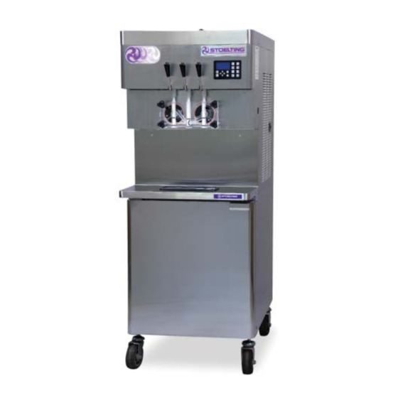
SECTION 1 DESCRIPTION AND SPECIFICATIONS DESCRIPTION The Stoelting U431 I2 fl oor model machine is pressure fed. It is equipped with fully automatic controls to provide a uniform product. This manual is designed to assist qualifi ed service per- sonnel and operators with installation, operation and maintenance of the U431 I2. -
Page 8: Specifi Cations
Ideal EWT of 50°-70°F. The machine space on all sides and open at the top. requires 6” (15,2 cm) air space on all sides for the cabinet refrigeration system. Hopper Volume Two - 8 gallon (30,28 liters) Owner’s Manual #513660 U431 I2 Model Machines... -
Page 9: Installation Instructions
208V position. customer must place a claim for damages and/or short- NOTE ages in shipment with the carrier. Stoelting, Inc. cannot Supply voltage must be checked to make sure the make any claims against the carrier. -
Page 10: Mix Pump
Off button on the touchpad. Risk of Product Damage Air/Mix Tee must remain below the black cover clamp. If the Tee is above the pump, mix may drain into the air compressor resulting in pump damage. Owner’s Manual #513660 U431 I2 Model Machines... - Page 11 The bag that is connected nearest the outlet of the manifold will drain last and should be placed at the back of the mix container. The mix low level indicator relies on proper bag placement. Owner’s Manual #513660 U431 I2 Model Machines...
-
Page 12: Mix Low Level Indicator Adjustment
(closest Retaining to the mix outlet) to the Clip mix bag in the back of the mix container. Manifold Adapter Manifold Plug Bag Adapter Figure 2-4 Bag Connection System (Optional) Owner’s Manual #513660 U431 I2 Model Machines... - Page 13 Figure 2-9 On the User Preferences screen move the cursor to the Contact Information USB Update and press the SEL button. Press the left arrow button until the Current Status screen is displayed. Owner’s Manual #513660 U431 I2 Model Machines...
- Page 14 Scrape the top of the cup with a straight edge. Weigh the fi lled cup. Calculate the overrun using the following equation: Change the value in the control. Press the left arrow button until the Current Status screen is displayed. Owner’s Manual #513660 U431 I2 Model Machines...
-
Page 15: Initial Set-Up And Operation
Do not operate under unsafe operating conditions. Never operate the machine if unusual or excessive noise or vibration occurs. IntelliTec2™ Control (See Figure 3-2) Dispense Rate Adjuster Figure 3-1 U431 I2 Machine Controls Owner’s Manual #513660 U431 I2 Model Machines... -
Page 16: Disassembly Of Parts
Remove the compression spring and push the air bleed valve through the rear of the front door. Owner’s Manual #513660 U431 I2 Model Machines... -
Page 17: Cleaning Disassembled Parts
Remove the drip trays from the front panel. Clean and replace the drip trays. Figure 3-5 Rear Seal Assembly Owner’s Manual #513660 U431 I2 Model Machines... -
Page 18: Assembling The Machine
Install the remaining plastic fl ights, push the auger processing equipment be certifi ed for this use. into the freezing cylinder and rotate slowly until the auger engages the drive shaft. Owner’s Manual #513660 U431 I2 Model Machines... -
Page 19: Sanitizing
Press the PUSH TO FREEZE button. Figure 3-8 Air Bleed Valve Let sanitizing solution fi ll the freezing cylinder to the air bleed valve, then close the valve by pulling it out to lock in place. Owner’s Manual #513660 U431 I2 Model Machines... -
Page 20: Mix Information
fi nished product that is unsatisfactory. To retard bacteria growth in dairy based mixes, the best storage temperature range is between 33° to 38°F (0.5° to 3.3° C). Intake Discharge Figure 3-9 Mix Pump Hose Routing Owner’s Manual #513660 U431 I2 Model Machines... -
Page 21: Mix Pump Cleaning
Make sure the display shows the freezing cylinders and pump are off. If they are not, press the On/Off button and Pump button to turn them off. Figure 3-10 Mix Pump Removable Parts Owner’s Manual #513660 U431 I2 Model Machines... - Page 22 Owner’s Manual #513660 U431 I2 Model Machines...
-
Page 23: Maintenance And Adjustments
The hose timer must be reset each time the hose is Off. Disconnect power sources/circuit breakers. repositioned or replaced to keep an accurate record Remove the back panel from the machine. of the hose service time. Owner’s Manual #513660 U431 I2 Model Machines... -
Page 24: Mix Pump Hose Replacement
Refer to Section 4.2 H-N for instructions on resetting the timer. Pickup 12” to 14” Figure 4-2 Pump Hose Reposition Owner’s Manual #513660 U431 I2 Model Machines... -
Page 25: Fine Consistency Adjustment
Do not let cleaning solution stand in machine barrel or mix pump during the shutdown period. Remove, disassemble, and clean the front door, auger shaft, and mix pump. Leave disassembled during the shutdown period. Owner’s Manual #513660 U431 I2 Model Machines... - Page 26 Drain the water supply line coming to the machine. Disconnect the water outlet fi tting. Disconnect the machine from the source of the electrical supply in the building. Owner’s Manual #513660 U431 I2 Model Machines...
-
Page 27: Troubleshooting
To return the machine to normal operation, any error If the error persists after attempting to clear it, causing condition must be corrected and the power to contact your Authorized Stoelting Distributor for the affected freezing cylinder must be cycled. Turn the further assistance. - Page 28 On/Off button for the cylinder to turn to turn if off then back on. If the error persists, if off then back on. If the error persists, contact contact your Authorized Stoelting Distributor for your Authorized Stoelting Distributor for further further assistance.
-
Page 29: Troubleshooting - Machine
3 Chipped or worn spigot o-rings. 3 Replace o-rings. Front door leaks. 4 O-rings or spigot installed wrong. 4 Remove spigot and check o-ring. 5 Inner spigot hole in front door nicked 5 Replace front door. or scratched. Owner’s Manual #513660 U431 I2 Model Machines... -
Page 30: Troubleshooting - Mix Pump
2 Tighten all hose clamps. Overrun too low or no overrun. 3 Air compressor not pumping air. 3 Contact local Stoelting Distributor. 4 Air check valve in backwards. 4 Check arrow for direction of fl ow. Owner’s Manual #513660 U431 I2 Model Machines... - Page 31 4 Pump motor not running. 4 Press the Pump button to turn the pump On. Air exiting mix pick- 1 Pickup tube check valve missing. 1 Contact local Stoelting Distributor. up hose. 1 Overrun setting too high. 1 Decrease overrun setting.
- Page 32 Owner’s Manual #513660 U431 I2 Model Machines...
-
Page 33: Replacement Parts
Decal - Attention Heat Sensitive 324686 Decal - Danger Automatic Start 324728 Decal - Contactor Identifi cation 324803 Decal - Domed Stoelting Logo (Large) (Header Panel) 324804 Decal - Domed Stoelting Swirl (Header Panel) 324887 Decal - Boost Transformer 508048... -
Page 34: Auger Shaft And Front Door Parts
Adapter - Rear Seal (Code 1)(Requires #624678)(Ser. #0 - #3899712HB) 2 2202179 Auger Shaft Auger Shaft (Ser. #0 - #3899712HB) 2187811 Spigot Body - Center 2187812 Spigot Body - Outer 4151178 Auger Shaft Auger Shaft (Ser. #3899812HB Plus) Owner’s Manual #513660 U431 I2 Model Machines... -
Page 35: Cab Tubing
1172864 Check Valve - Mix In Line (Outer) 2177274 Clip - Retaining (Mix Probe To Cover) 2203792 Pick-Up Tube - Mix 3177229 Cover - Rear (Mix Container) 3177262 Cover - Front (Mix Container) Owner’s Manual #513660 U431 I2 Model Machines... - Page 36 Owner’s Manual #513660 U431 I2 Model Machines...
- Page 37 Stoelting’s sole obligations, and Buyer’s sole remedies, for any breach of this warranty shall be, at Stoelting’s option, one of the following: repair or replacement of the affected component at Stoelting’s plant in Kiel, Wisconsin, or refund of the purchase price of the affected Equipment. Stoelting, through an Authorized Stoelting Provider, will deinstall/reinstall the affected component from/into the equipment (“Labor”) for the period listed below in the Warranty...
- Page 38 Costs not covered by the Stoelting Travel Pay policy. Stoelting covers only the first trip travel which is a flat rate by mileage one- way from the service company’s home location to the job site. The flat rate is calculated as follows:...