HP 333A Technical Manual
Distortion analyzer
Hide thumbs
Also See for 333A:
- Operating and service manual (88 pages) ,
- Operating manual (214 pages) ,
- Operating and service manual (20 pages)

Related Manuals for HP 333A


Summary of Contents for HP 333A
- Page 1 TM 11-6625-1576-15 DEPARTMENT OF THE ARMY TECHNICAL MANUAL ORGANIZATIONAL, DS, GS, AND DEPOT MAINTENANCE MANUAL DISTORTION ANALYZER HEWLETT-PACKARD MODELS 333A AND 334A HEADQUARTERS, DEPARTMENT OF THE ARMY MAY 1967...
- Page 2 TM 11-6625-1576-15 WARNING DANGEROUS VOLTAGES EXIST IN THIS EQUIPMENT Be careful when working on the power supply and on the 115-volt ac line connections. DO NOT TAKE CHANCES !
-
Page 3: Table Of Contents
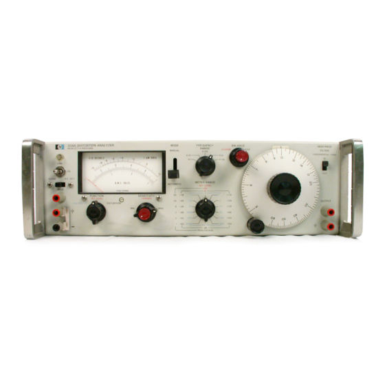
O r g a n i z a t i o n a l , D S , G S , a n d D e p o t M a i n t e n a n c e DISTORTION ANALYZER, HEWLETT-PACKARD MODELS 333A AND 334A... - Page 5 TM 11-6625-1576-15 Section 1 Model 333A/334A Figure 1-1 and Table 1-1 Figure 1-1. Model 333A Distortion Analyzer Table 1-1. Specifications...
- Page 6 TM 11-6625-1576-15 Section I Model 333A/334A Table 1-1 Table 1-1. Specifications (Cont ‘d)
-
Page 7: General Information
TM 11-6625-1576-15 SECTION I GENERAL INFORMATION 1 - A . 1 S c o p e T h i s m a n u a l i n c l u d e s i n s t a l l a t i o n a n d o p e r a t i o n i n s t r u c t i o n s... -
Page 9: Description
1-8. OPTION. quires only O. 3 v rms for the 100% set level reference. 1-9. Option 0l is a standard -hp- Model 333A or 334A The distortion characteristics can be monitored at the with a special meter and meter amplifier, compen-... -
Page 11: Installation
2-1. INTRODUCTION. 2-14. RACK INSTALLATION. 2-2. This section contains information and instruc- 2-15. The Model 333A/334A may be rack mounted by tions necessary for the installation and shipping of the using the 5“ RackMount Kit (-hp- Part No. 5060-0775). Models 333A/334A Distortion Analyzers. Included... - Page 12 TM 11-6625-1576-15 Model 333A/334A Section III Figure 3-1 Figure 3-1. Front and Rear Panel Description 3 - 0...
-
Page 13: Operating Instructions
Maximum Error Total Distortion In Meter Indication Distortion 333A and 334A have a dc isolation of ±400 vdc from the external chassis with the shorting bar, (item 16 , 2. 5% +0. 11 X O. 025 = 0.025 +0. 0027 = Figure 3-1), disconnected. -
Page 14: Operating Procedures
Meter indication is in conjunction with METER RANGE selector. For example, if meter indicates 3-17. The 333A and 334A Distortion Analyzers can be .4 and METER RANGE selector is on 1% position, operated from an ac power source ( 115/230 volt) or a distortion measured is 0.4%. - Page 15 TM 11-6625-1576-15 Section III Model 333A/334A Paragraphs 3-23 to 3-27 3-25. The 333A and 334A perform as general purpose c. Perform steps j through n of Paragraph 3-19. AC Voltmeters when the FUNCTION selector is set to VOLTMETER position. d. Repeat steps m and n until no further reduction n meter indication can be obtained.
- Page 16 T M 1 1 - 6 6 2 5 - 1 5 7 6 - 1 5 S e c t i o n F i g u r e 4 - 1 Model 333A/334A F i g u r e 4 - 1 . B l o c k...
-
Page 17: Theory Of Operation
In addition to the 4-1. OVERALL DESCRIPTION. visual indication provided by the meter, the OUTPUT 4-2. Models 333A and 334A Distortion Analyzers in- terminals provide a means of monitoring the distortion clude an impedance converter, a rejection amplifier, components. -
Page 18: Rejection Amplifier Circuit
TM11-6625-1576-15 Section IV Model 333A/334A Paragraphs 4-13 to 4-25 and Figure 4-2 the emitter of A2Q3 to the collector of A2Q2. Overall negative feedback from the emitter circuit of A2Q4 to the source of A2Q1 results in unity gain from the im- pedance converter. - Page 19 TM 11-6625-1576-15 Section IV Model 333A/334A Paragraphs 4-26 to 4-27 and Figure 4-3 resistance of A6V2 through A6V5, making variation 4-26. The operation of the reactive branch control loop in resistance less than on the two lower ranges. is similar to that of the resistive branch. The phase...
- Page 20 TM 11-6625-1576-15 Section IV Paragraphs 4-28 to 4-35 and Figures 4-4 to 4-5 Figure 4-4. Wien Bridge Circuit and Rejection Characteristics 4-28. When the bridge circuit is tuned and balanced, positive half of the signal will be passed, and if it is out of phase, the negative half will be passed.
-
Page 21: High Pass Filter
TM 11-6625-1576-15 Section IV Paragraphs 4-36 to 4-45 and Figure 4-6 Figure 4-6. Rejection Amplifier Block Diagram and Typical Frequency Rejection Characteristic the calibration network on the 300 v range to extend first stage of amplification, A3Q4, is a field effect the passband of the amplifier. - Page 22 TM 11-6625-1576-15 Model 333A/334A Section IV Figure 4-7 Figure 4-7. Bandwidth Versus Null Depth 4 - 6...
-
Page 23: Power Supply Circuit
TM 11-6625-1576-15 model 333A/334A Section IV Paragraphs 4-46 to 4-52 and Figure 4-8 Figure 4-8. Simplified Metering Circuit 4-46. POWER SUPPLY CIRCUIT. 4-50. Diodes A1CR5 and A1CR6 are coupling and pro- tection diodes for external battery supplies. The diodes 4-47. The power supply circuit (refer to Figure 6-5) - Page 24 TM 11-6625-1576-15 Model 333A/334A Section V Table 5-1 Table 5-1. Test Equipment Required 5 - 0...
-
Page 25: Vmaintenance
Set Wave Analyzer controls (-hp - Model 302A) as follows: 5-4. Test equipment used in the calibration of the 333A SCALE VALUE ..RELATIVE and 334A is given in Table 5-1, Test Equipment Re- MAX INPUT VOLTAGE . -
Page 26: Second Harmonic Accuracy Check
FREQUENCY RANGE ... X1 Frequency Dial ....20 Connect 333A/334A as shown in Figure 5-2. METER RANGE Selector ..0 DB Set Distortion Analyzer controls as follows: FUNCTION Selector . -
Page 27: Frequency Calibration Accuracy Check
Adjust Distortion Analyzer BALANCE controls CHECK. for a null indication on the meter. Repeat steps g and h until a null is reached. a. Connect 333A/334A as shown in Figure 5-3. Figure 5.-3. Test Setup for Frequency Calibration Accuracy Check... -
Page 28: Input Resistance Check
FUNCTION Selector ..VOLTMETER METER RANGE Selector ..1 VOLT Connect an L - C meter to the 333A/334A and measure the input capacitance. c. Apply ac power to dc power supply and set for 400 v. -
Page 29: Voltmeter Accuracy Check
5-17. VOLTMETER ACCURACY CHECK 5-18. HIGH PASS FILTER CHECK a. Connect Voltmeter Calibrator (-hp- Model 738B) Connect the 333A/334A as shown in Figure 5-6. and Variable Line Transformer (Superior Type UC1M) to Distortion Analyzer as shown in Figure 5-5. Re-... -
Page 30: Voltmeter Frequency Response Check
Table 5-5. Repeat step g after each setting. The Dis - 5-21. AM DETECTOR CHECK (Model 334A only). tortion Analyzer meter shall indicate 0.9 ± the toler- a. Connect Signal Generator (hp- Model 606A) 50 ances indicated. RF OUTPUT to Distortion Analyzer RF INPUT. -
Page 31: Adjustment And Calibration Procedure
5-23. The following is a complete adjustment and cali- c. When pointer is exactly on zero, rotate adjust- bration procedure for the 333A and 334A. Before proceeding with these adjustments, the Performance ment screw approximately 2 degrees counterclockwise. - Page 32 TM11-6625-1576-15 Model 333A/334A Section Figure 5-8 Figure 5-8 Component and Adjustment Location...
-
Page 33: A3R16 And A3R30 Distortion Adjust
METER RANGE Switch . . SET LEVEL Range 5-28. A3R16 AND A3R30 DISTORTION ADJUST. FREQUENCY RANGE Selector ..X1K a. Connect test equipment to the 333A/334A as SENSITIVITY Selector ..Position 5 shown in Figure 5-9. -
Page 34: Voltmeter Gain Adjustments
Adjust S3C6 (VOLTAGE ADJUSTMENT. CAL at 2.5 Mc O. 3 v RANGE trimmer) for a Distor- a. Connect the test equipment to the 333A/334A as tion Analyzer meter indication of O. 9 on the 1.0 scale. shown in Figure 5-6. -
Page 35: Troubleshooting Procedures
AND SUBSEQUENT DETERIORATION TO 1.0 scale. THE OPERATION OF THE INSTRUMENT. h. Repeat steps d through f, calibrating sensitivity 5-35. Conduct a visual check of the 333A/334A for at the settings indicated in Table 5-7. possible burned or loose components, loose connec- NOTE... - Page 36 TM 11-6625-1576-15 Model 333A/334A Section V Table 5-8 5-12...
-
Page 37: Servicing Rotary Switches
Section V Paragraph 5-43 to 5-45 d. To replace components, shape new leads and The -hp- Part Number for the assembly is marked on insert them in lead holes. Reheat with soldering iron the circuit board to identify it. and add a small amount of new solder as required to insure a good electrical connection. - Page 38 TM 11-6625-1576-15 Model 333A/334A S e c t i o n V T a b l e 5 - 9 5-14...
- Page 39 1 1 - 6 6 2 5 - 1 5 7 6 - 1 5 S e c t i o n V Figure 5-10 Figure 5-10. Troubleshooting Logic 5-15...
- Page 40 TM 11-6625-1576-15 Model 33A/334A Section V Table 5-10 Figure 5-11 Frequency Tuning Assembly 5-16...
- Page 41 TM11-6625-1576-15 Section VI Paragraphs 6-1 to 6-2 S E C T I O N V I SCHEMATICS Main signal paths and significant feedback paths are 6-1. SCHEMATIC DIAGRAMS. identified (refer to notes on the schematic diagrams). An A5 board component location diagram is included, 6-2.
- Page 42 TM 11-6625-1576-15 Section VI Model 333A/334A Figure 6-1 Figure 6-1. P/O Internal Wiring Data...
- Page 43 By Order of the Secretary of the Army: HAROLD K. JOHNSON, General, United States Army, Chief of Staff. Offical: KENNETH G. WICKHAM Major General, United States Army, The Adjutant General. Distribution: Active Army : Eighth USA (5) USAMB (1) SAAD (5) USACDCEC (1) TOAD (6) USACDCCEA (1)
- Page 53 PIN : 016265-000...