Advertisement
Quick Links
SOLID STATE CROSSING
CONTROLLER IV (SSCC IV) , 91215
PSO 4000 CROSSING
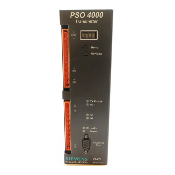
PSO 4000 TRANSMITTER, 7A471
ASSEMBLY, 7A474
+
+
+
Menu
Navigate
+
+
+
+
+
TX Enable
OUT
B
B
N
N
IN1
+
IN2
+
Health
Power
+
Diagnostic
+
Port
+
Made in USA
WOT (RX1)
TUNED RECEIVER
COUPLER, 7A355-f
MIN.#9 AWG TWISTED PAIR
-7-
NOTES
1.
PSO 4000 TRACK WIRES MAY BE
#9 A.W.G. FOR LENGTHS UP TO
100 FEET. FOR LENGTHS BETWEEN
100 AND 300 FEET, TRACK WIRES
SHOULD BE #6 A.W.G. IF LENGTHS
EXCEED 300 FEET, REFER TO
SECTION 7.2.3 FOR TRACK WIRE
SELECTION AND SECTION 3.3 FOR
COUPLER USAGE AND
INSTALLATION.
2.
PSO 4000 UNIT INPUTS AND
OUTPUTS ARE CONNECTED PER
THE RAILROAD'S OR AGENCY'S
WRITTEN INSTRUCTIONS.
3.
WOT, EOT, AND OXT MUST EACH
BE SET TO SEPARATE PSO AND
ISLAND FREQUENCIES.
SET OUT1= XR TO UTILIZE THE
4.
SSCC.
5.
SSCC UNIT MAY BE SSCC III, SSCC
III (PLUS) OR SSCC IV. THE SSCC
PSO 4000 TRANSMITTER, 7A471
IS WIRED PER THE RAILROAD'S
OR AGENCY'S APPROVED WIRING
DIAGRAM.
+
LEGEND
= TWIST TWO TURNS PER FOOT
Menu
=
022700-1X EQUALIZER, H.D.
Navigate
=
022585-1X ARRESTER, H.D.
RX1
=
EARTH GROUND
RX2
+
Island
Stick
XR
+
RX1
RX2
Island
Island LOS
OUT1
B
OUT2
N
OUT3
IN1
IN2
Health
Power
Diagnostic
+
Port
EOT (RX2)
TUNED RECEIVER
COUPLER, 7A355-f
Made in USA
07-06_7A474_APP_DWG
07-08-09
MIN.#9 AWG TWISTED PAIR
-8-
QUICK REFERENCE GUIDE
INSTALL PSO 4000 CROSSING
ASSEMBLY MODULES
Document Number SIG-QG-10-06
Version A.1
The following procedure should be used when installing
Phase Shift Overlay 4000 (PSO 4000) Track Circuits utilizing
PSO 4000 Transmitter, 7A471 and PSO Crossing Assembly,
7A474.
WARNING
VERIFY
THAT
THE
TRANSMITTER'S
AND
ASSEMBLY'S
SOFTWARE,
AND
ADDRESS
FORMATS
SPECIFIED
BY
THE
RAILROAD'S
AGENCY'S
APPROVED
Menu
INSTALLATION DIAGRAM. FAILURE TO DO
Navigate
SO MAY LEAD TO INCORRECT OR UNSAFE
OPERATION OF THE TRACK CIRCUIT.
IF ANY RECEIVER IS CALIBRATED IN POOR
BALLAST CONDITIONS, IT MUST BE RE-
CALIBRATED WHEN BALLAST CONDITIONS
TX Enable
IMPROVE.
OUT
FAILURE TO FOLLOW THE RAILROAD'S OR
IN1
IN2
AGENCY'S
APPROVED
Health
INSTALLATION GUIDELINES REGARDING
Power
RECEIVER SETTINGS AND CALIBRATION
Diagnostic
MAY
LEAD
TO
POSSIBLE
Port
OPERATION OF THE TRACK CIRCUIT.
AFTER CALIBRATION, VERIFY THAT THE
Made in USA
TRACK CIRCUIT DE-ENERGIZES WHEN THE
TRACK CIRCUIT IS SHUNTED WITH THE
APPROPRIATE CALIBRATION RESISTANCE
(0.06, 0.2, 0.3, 0.4, OR 0.5 OHMS). FAILURE
TO DO SO MAY LEAD TO INCORRECT OR
UNSAFE
OPERATION
OF
CIRCUIT.
FOLLOWING INSTALLATION OR AFTER
ANY RECEIVER MENU CHANGES HAVE
BEEN MADE, RECALIBRATE THE RECEIVER
AND TEST FOR PROPER OPERATION PER
THE REQUIREMENTS SPECIFIED IN TABLE
7-2 AND TABLE 7-3 OF SIG-00-07-06, PSO
4000 I & I MANUAL.
©
Copyright
2010-2014 Siemens
All Rights Reserved
Perform the following steps to install the PSO 4000 units:
1.
Install and connect all PSO equipment in the Wayside
Signaling Station (WSS) per the railroad's or agency's
approved wiring or installation diagram.
2.
Connect all required wiring per the railroad's or
agency's approved wiring or installation diagram.
3.
Prior to beginning programming, verify LED
functionality using the *CHECK LED portion of the
TEST menu per Section 5.2.7.2. If any LED fails to light
following test, replace the unit.
4.
Program each unit by performing Set to Default. Then
proceed through the setup (SETP) menu to program
each unit per the railroad's or agency's approved
written instructions.
With each unit properly installed and programmed per
written instructions, calibrate the approaches (RX1 or RX2)
PSO
4000
as follows:
CROSSING
1.
When the track ballast is good, connect a test shunt
FREQUENCY,
(hardwire, 0.06-ohm, 0.2-ohm, or as required) across
ARE
AS
the track at the receiver track connections of the
OR
approach. When the ballast is poor, connect the shunt
WIRING
OR
across the track at a point 30 feet beyond the
receiver track connections of the approach. Verify
solid connections of the shunt to each rail.
Scroll down the Main Menu until CAL appears on the
display. Then:
•
Press the MENU Button for two (2) seconds until
RX1 (RX2) CAL appears.
Hold the MENU Button down until the release
•
(REL) message appears. Release the MENU Button
WIRING
OR
immediately once the release (REL) message
appears.
•
As soon as the MENU button is released, the
UNSAFE
armed (ARMD) message appears. Immediately
press and release the MENU Button as soon as
the ARMD message appears. This starts the
calibration process. If the MENU Button is not
pressed within two (2) seconds, the calibration
process cancels and the calibration process must
be restarted.
*RX1 (*RX2) CAL flashes during the calibration
•
THE
TRACK
process.
•
PASS or FAIL appears for two (2) seconds when
calibration is complete. When PASS appears,
continue to Step 3. If FAIL appears, the
CALIBRATION REQUIRED LED remains lit.
-2-
Advertisement

Summary of Contents for Siemens PSO 4000
- Page 1 Perform the following steps to install the PSO 4000 units: Install and connect all PSO equipment in the Wayside Signaling Station (WSS) per the railroad’s or agency’s approved wiring or installation diagram. QUICK REFERENCE GUIDE Connect all required wiring per the railroad’s or...
- Page 2 (refer to the LED fails to light, the calibration process has failed 21. Verify proper PSO 4000 operation by observing train transmitter’s track surge equipment. WARNING above). Inspect all equipment and (refer to the WARNING above).


