Rotel RA-1070 Technical Manual
Hide thumbs
Also See for RA-1070:
- Owner's manual (46 pages) ,
- Command list (1 page) ,
- Owner's manual (50 pages)
Advertisement
Quick Links
Download this manual
See also:
Owner's Manual
T echnical
Manual
Table of Contents
Specification...................................... 1
Parts List ........................................... 2~4
Adjustment........................................ 5
Safety Caution................................... 5
Case Outlines.................................... 5~6
PCB Assembly .................................. 6~8
Schematic Diagram .......................... 9~12
Specification
Continuous Power Output
(20 - 20 kHz, < 0.03%, 8 ohms)
Total Harmonic Distortion (20 Hz - 20 kHz)
Intermodulation Distortion(60 Hz : 7 kHz, 4:1) < 0.05% at rated power, 1/2 power or 1 watt
Frequency Response
Line Level inputs
Phono input
Damping Factor (20 - 20,000 Hz. 8 ohms)
Input Sensitivity / impedance
Line Level inputs
Phono input (MM)
Input Overload
Line Level inputs
Phono input (MM)
Preamplifier Output Maximum Voltage
Signal to Noise Ratio (IHF " A" weighted)
Line Level inputs
Phono input
Power Requirements
USA Version
European Version
Power Consumption
Dimensions (W x H x D)
Weight (net)
SHINSEN-BLD. 4F 10-10 SHINSEN-CHO, SHIBUYA-KU,
TOKYO 150-0045, JAPAN
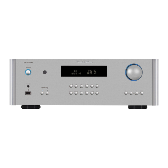
STEREO INTEGRATED AMPLIFIER
RA-1070
100 watts/channel
< 0.03% at rated power, 1/2 power, or 1 watt
4 Hz - 100 kHz, ± 3 dB
20 Hz - 20 kHz, ± 0.5 dB
400
150 mV / 33 kohms
1.2 mV / 68 kohms
5V
70 mV
1 V
102 dB
70 dB
115 Volts, 60 Hz
230 Volts, 50 Hz
400 Watts
430 x 121 x 360 mm
16
x4
x 14
15/16
3/4
3/16
10.3 kg, 22.7 lbs.
inches
Serial. NO.
Beginning
Y-339A-01015C/S-S
Advertisement

Related Manuals for Rotel RA-1070


Summary of Contents for Rotel RA-1070
-
Page 1: Table Of Contents
T echnical STEREO INTEGRATED AMPLIFIER RA-1070 Manual Table of Contents Specification........1 Parts List ........... 2~4 Adjustment........5 Safety Caution........5 Case Outlines........5~6 PCB Assembly ........6~8 Schematic Diagram ......9~12 Specification Continuous Power Output 100 watts/channel (20 - 20 kHz, < 0.03%, 8 ohms) Total Harmonic Distortion (20 Hz - 20 kHz) <... -
Page 2: Parts List
Parts List-1 SYMBOL PARTS NO. DESCRIPTION SYMBOL PARTS NO. DESCRIPTION X-1297-01 PCB ASSEMBLY C453.454 041 25BGF100M CAPACITOR ELEC.25V100UF L601.602 021 TRL-331 SPEAKER COIL C501.502 041 50BGF10M CAPACITOR ELEC.50V10UF 066 4TR-2408#3 4P PINJACK C503.504 044 FSC160V470H CAPACITOR STYROL 160V47PF Q619.620 033 TC3478A-LKU TRANSISTOR(2SC3478A-LKU) C505.506 041 50BGF10M... - Page 3 Parts List-2 SYMBOL PARTS NO. DESCRIPTION SYMBOL PARTS NO. DESCRIPTION R684 054 TMF4701 RESISTOR METAL 4.7K R427.428 054 TMFR4100R RESISTOR METAL 1% 100R R685 054 TMF1003 RESISTOR METAL 100K R429-432 054 MF16-1003-A RESISTOR METAL 100K R686 053 CR16-474J-A RESISTOR CARBON 470K RY406-408 063 A24W-K RELAY(FUNCTION)
- Page 4 Parts List-3 SYMBOL PARTS NO. DESCRIPTION SYMBOL PARTS NO. DESCRIPTION X-1298-02 PCB ASSEMBLY IC702 C905-907 043 TC500V103 CAPACITOR CERA.500V0.01UF IC904 031 HIN232CP IC(TRANSMITTER RECEIVER) C914 043 TC500V103 CAPACITOR CERA.500V0.01UF Q907 031 PC817B IC(PHOTO COUPLER) C923-930 043 TC500V103 CAPACITOR CERA.500V0.01UF R914 032 TC536-FG TRANSISTOR(2SC536K-FG) D901.902...
-
Page 5: Adjustment
Adjustment PCB Assembly Instruments : DC milli–voltmeter Notes : Prior to Bias Adjustment, run about 5minutes with rated output(8ohms) and warm up Power Transistor and Heat Sink. Set input off. Step Coupling Adjust Adjust for X-1297-01 PCB R641 X-1297-03 PCB VR601 DC milli–voltmeter reads 5mV X-1297-01 PCB... - Page 6 PCB Assembly...
-
Page 7: Schematic Diagram
Schematic Diagram... -
Page 8: Schematic Diagram
Schematic Diagram...