Table of Contents
Advertisement
Quick Links
This document describes the main features and functionality of the evaluation module (EVM) board for the
devices.
The ONET1131EC is a 11.7-Gbps transceiver with an integrated limiting amplifier and a modulator driver.
The EVM can be used to evaluate the performance of the parts in conjunction with an electroabsorptive
modulated laser (EML) transmit optical subassembly (TOSA) and a receive optical subassembly (ROSA)
in standard XMD-compliant packages.
The EVM is controlled with a graphical user interface (GUI).
Throughout this document, the images shown may represent the ONET1130Ex. Those images are
representative of the boards and parts on the ONET1131EC.
spacer
1
2
3
4
4.1
4.2
5
6
7
7.1
7.2
1
2
3
4
5
6
7
8
9
10
11
12
13
14
15
16
SLLU256 - October 2016
Submit Documentation Feedback
ONET1131EC Evaluation Module
...................................................................................................
.........................................................................................................
............................................................................................................
.........................................................................................................
..............................................................................................................
.............................................................................................
.........................................................................................
.........................................................................................................
....................................................................................................
.......................................................................................
.........................................................................................
.....................................................................................................
.................................................................................................................
........................................................................................
...................................................................................................
...........................................................................................
..................................................................................................
..........................................................................................
...................................................................................................
.....................................................................................
........................................................................................
..........................................................................................................
..........................................................................................................
..........................................................................................................
Copyright © 2016, Texas Instruments Incorporated
Contents
List of Figures
.......................................................................
User's Guide
SLLU256 - October 2016
........................................
.......................................
ONET1131EC Evaluation Module
2
2
3
6
8
10
13
13
15
15
18
2
3
4
5
6
7
8
9
10
11
12
13
14
15
16
17
1
Advertisement
Table of Contents

Related Manuals for Texas Instruments ONET1131EC


Summary of Contents for Texas Instruments ONET1131EC
-
Page 1: Table Of Contents
This document describes the main features and functionality of the evaluation module (EVM) board for the devices. The ONET1131EC is a 11.7-Gbps transceiver with an integrated limiting amplifier and a modulator driver. The EVM can be used to evaluate the performance of the parts in conjunction with an electroabsorptive modulated laser (EML) transmit optical subassembly (TOSA) and a receive optical subassembly (ROSA) in standard XMD-compliant packages. -
Page 2: Hardware And Equipment
9. Electrical cables with banana jack connections EVM Block Diagram Figure 1 represents the block diagram of the ONET1131EC EVM. The board is designed to be powered from a 2.5-V supply using cables with banana jacks. 3.3 V IN Optical... -
Page 3: Evm Connections
EVM board. 3.3-V Power Source for Receiver Outputs ROSA Transmitter Inputs 2.5-V Power Source USB Dongle Connector Figure 2. ONET1131EC EVM Connections SLLU256 – October 2016 ONET1131EC Evaluation Module Submit Documentation Feedback Copyright © 2016, Texas Instruments Incorporated... -
Page 4: Tosa And Eml Connections For Tec Controller
TOSA thermistor, and the TEC+ and TEC– connections to the TEC controller. TEC+ TECí Vea GND TOSA Thermistor + Thermistor í Figure 3. TOSA and EML Connections for TEC Controller ONET1131EC Evaluation Module SLLU256 – October 2016 Submit Documentation Feedback Copyright © 2016, Texas Instruments Incorporated... -
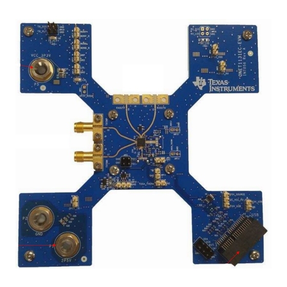
Page 5: Main Evm Connections
EML bias and TEC controller. ROSA and Receiver connections are not available on the ONET131EC-EVM. Figure 4. Main EVM Connections SLLU256 – October 2016 ONET1131EC Evaluation Module Submit Documentation Feedback Copyright © 2016, Texas Instruments Incorporated... -
Page 6: Measurement Setup
9. Connect the TOSA to the optical input of a DCA through a single-mode fiber patch cord. A typical setup is shown in Figure Figure 5. Typical Setup ONET1131EC Evaluation Module SLLU256 – October 2016 Submit Documentation Feedback Copyright © 2016, Texas Instruments Incorporated... -
Page 7: Low Level Register Interface Page
10. Run the GUI by clicking the ONET1130EC GUI shortcut icon on the desktop. The Low Level Register Interface page appears (Figure NOTE: The ONET1130EC EVM GUI software works with the ONET1131EC EVM. Figure 6. Low Level Register Interface Page SLLU256 – October 2016... -
Page 8: Open Loop Operation Without Fault Detection Or Digital Monitoring
2. Go to the Core Configuration page as shown in Figure Figure 7. Core Configuration Page 3. Set the TX Bias Current Control to Open Loop. 4. Enable the Laser Bias Current. ONET1131EC Evaluation Module SLLU256 – October 2016 Submit Documentation Feedback Copyright © 2016, Texas Instruments Incorporated... -
Page 9: Transmitter Configuration Page
10. If the transmitter modulation current is less than approximately 0xC0, then TI recommends using the slow edge speed mode as selected with the TX edge speed selection bit. However, the need for using this mode is TOSA dependent. SLLU256 – October 2016 ONET1131EC Evaluation Module Submit Documentation Feedback Copyright © 2016, Texas Instruments Incorporated... -
Page 10: Closed Loop Operation With Fault Detection And Digital Monitoring
7. In the Analog to Digital Conversion box, enable the ADC and ADC oscillator and select the desired parameter to be monitored using the drop-down box. ONET1131EC Evaluation Module SLLU256 – October 2016 Submit Documentation Feedback Copyright © 2016, Texas Instruments Incorporated... -
Page 11: Transmitter Configuration Page
16. Go to the Core Configuration page and toggle the Enable Laser Bias Current bit. This disables the fault and restores the transmitter output. SLLU256 – October 2016 ONET1131EC Evaluation Module Submit Documentation Feedback Copyright © 2016, Texas Instruments Incorporated... -
Page 12: Read Only Status Page
Figure 11. Read Only Status Page 18. Click the Refresh button and read the value of the Output Representation of the ADC Input Source. ONET1131EC Evaluation Module SLLU256 – October 2016 Submit Documentation Feedback Copyright © 2016, Texas Instruments Incorporated... -
Page 13: Led Indicators
Transmitter Cross Point = 0xB0 • TX and RX CDRs Enabled A typical unfiltered eye diagram is shown in Figure Figure 12. Unfiltered Transmitter Eye Diagram SLLU256 – October 2016 ONET1131EC Evaluation Module Submit Documentation Feedback Copyright © 2016, Texas Instruments Incorporated... -
Page 14: Filtered Transmitter Eye Diagram
Typical Performance Results www.ti.com A typical filtered eye diagram is shown in Figure Figure 13. Filtered Transmitter Eye Diagram ONET1131EC Evaluation Module SLLU256 – October 2016 Submit Documentation Feedback Copyright © 2016, Texas Instruments Incorporated... -
Page 15: Schematics And Bill Of Materials
GND2 GND3 100pF GND4 0.1uF 2 Pin Header GND_PAD 0.1uF ONET1131Ex 10uF Copyright © 2016, Texas Instruments Incorporated Figure 14. Schematic (1 of 3) SLLU256 – October 2016 ONET1131EC Evaluation Module Submit Documentation Feedback Copyright © 2016, Texas Instruments Incorporated... -
Page 16: Schematic (2 Of 3)
0201 2P5V_TX MOD_AN_OFFSET JMP1 0.1uF 0.1uF 0402 2 Pin Header Copyright © 2016, Texas Instruments Incorporated OFFSET VOLTAGE Figure 15. Schematic (2 of 3) ONET1131EC Evaluation Module SLLU256 – October 2016 Submit Documentation Feedback Copyright © 2016, Texas Instruments Incorporated... -
Page 17: Schematic (3 Of 3)
DUT as MMSTA55 possible. TMP422 I2C Device Address = 1001100 Copyright © 2016, Texas Instruments Incorporated 0x98 with Write Bit 0x99 with Read Bit Figure 16. Schematic (3 of 3) SLLU256 – October 2016 ONET1131EC Evaluation Module Submit Documentation Feedback Copyright ©... -
Page 18: Bill Of Materials
Schematics and Bill of Materials www.ti.com Bill of Materials Table 2 lists the ONET1131EC EVM BOM. Table 2. ONET1131EC EVM Bill of Materials Item Reference Value Part Number Manufacturer PCB Footprint Notes 2200pF GRM033R61A222KA01D Murata Electronics North America 0201 2200pF 10V Ceramic Capacitor X5R 0201 (0603 Metric) 0.024" L x 0.012" W (0.60mm x 0.30mm) - Page 19 Schematics and Bill of Materials www.ti.com Table 2. ONET1131EC EVM Bill of Materials (continued) Item Reference Value Part Number Manufacturer PCB Footprint Notes R7, R6 RC0402FR-07100RL Yageo 0402 RES SMD 100 OHM 1% 1/16W 0402 R9, R11 RC0402FR-07249RL Yageo 0402...
- Page 20 Schematics and Bill of Materials www.ti.com Table 2. ONET1131EC EVM Bill of Materials (continued) Item Reference Value Part Number Manufacturer PCB Footprint Notes DNI_EML_TOSA 162X_TOSA Note: TI will assemble the TOSA Q5, Q4 FDV301N FDV301N Fairchild SOT23_3 MOSFET N-CH 25V 220MA SOT-23...
- Page 21 STANDARD TERMS AND CONDITIONS FOR EVALUATION MODULES Delivery: TI delivers TI evaluation boards, kits, or modules, including any accompanying demonstration software, components, or documentation (collectively, an “EVM” or “EVMs”) to the User (“User”) in accordance with the terms and conditions set forth herein. Acceptance of the EVM is expressly subject to the following terms and conditions.
- Page 22 FCC Interference Statement for Class B EVM devices NOTE: This equipment has been tested and found to comply with the limits for a Class B digital device, pursuant to part 15 of the FCC Rules. These limits are designed to provide reasonable protection against harmful interference in a residential installation.
- Page 23 【無線電波を送信する製品の開発キットをお使いになる際の注意事項】 開発キットの中には技術基準適合証明を受けて いないものがあります。 技術適合証明を受けていないもののご使用に際しては、電波法遵守のため、以下のいずれかの 措置を取っていただく必要がありますのでご注意ください。 1. 電波法施行規則第6条第1項第1号に基づく平成18年3月28日総務省告示第173号で定められた電波暗室等の試験設備でご使用 いただく。 2. 実験局の免許を取得後ご使用いただく。 3. 技術基準適合証明を取得後ご使用いただく。 なお、本製品は、上記の「ご使用にあたっての注意」を譲渡先、移転先に通知しない限り、譲渡、移転できないものとします。 上記を遵守頂けない場合は、電波法の罰則が適用される可能性があることをご留意ください。 日本テキサス・イ ンスツルメンツ株式会社 東京都新宿区西新宿6丁目24番1号 西新宿三井ビル 3.3.3 Notice for EVMs for Power Line Communication: Please see http://www.tij.co.jp/lsds/ti_ja/general/eStore/notice_02.page 電力線搬送波通信についての開発キットをお使いになる際の注意事項については、次のところをご覧くださ い。http://www.tij.co.jp/lsds/ti_ja/general/eStore/notice_02.page SPACER EVM Use Restrictions and Warnings: 4.1 EVMS ARE NOT FOR USE IN FUNCTIONAL SAFETY AND/OR SAFETY CRITICAL EVALUATIONS, INCLUDING BUT NOT LIMITED TO EVALUATIONS OF LIFE SUPPORT APPLICATIONS.
- Page 24 Notwithstanding the foregoing, any judgment may be enforced in any United States or foreign court, and TI may seek injunctive relief in any United States or foreign court. Mailing Address: Texas Instruments, Post Office Box 655303, Dallas, Texas 75265 Copyright © 2015, Texas Instruments Incorporated...
- Page 25 STANDARD TERMS FOR EVALUATION MODULES Delivery: TI delivers TI evaluation boards, kits, or modules, including any accompanying demonstration software, components, and/or documentation which may be provided together or separately (collectively, an “EVM” or “EVMs”) to the User (“User”) in accordance with the terms set forth herein.
- Page 26 FCC Interference Statement for Class B EVM devices NOTE: This equipment has been tested and found to comply with the limits for a Class B digital device, pursuant to part 15 of the FCC Rules. These limits are designed to provide reasonable protection against harmful interference in a residential installation.
- Page 27 【無線電波を送信する製品の開発キットをお使いになる際の注意事項】 開発キットの中には技術基準適合証明を受けて いないものがあります。 技術適合証明を受けていないもののご使用に際しては、電波法遵守のため、以下のいずれかの 措置を取っていただく必要がありますのでご注意ください。 1. 電波法施行規則第6条第1項第1号に基づく平成18年3月28日総務省告示第173号で定められた電波暗室等の試験設備でご使用 いただく。 2. 実験局の免許を取得後ご使用いただく。 3. 技術基準適合証明を取得後ご使用いただく。 なお、本製品は、上記の「ご使用にあたっての注意」を譲渡先、移転先に通知しない限り、譲渡、移転できないものとします。 上記を遵守頂けない場合は、電波法の罰則が適用される可能性があることをご留意ください。 日本テキサス・イ ンスツルメンツ株式会社 東京都新宿区西新宿6丁目24番1号 西新宿三井ビル 3.3.3 Notice for EVMs for Power Line Communication: Please see http://www.tij.co.jp/lsds/ti_ja/general/eStore/notice_02.page 電力線搬送波通信についての開発キットをお使いになる際の注意事項については、次のところをご覧ください。http:/ /www.tij.co.jp/lsds/ti_ja/general/eStore/notice_02.page 3.4 European Union 3.4.1 For EVMs subject to EU Directive 2014/30/EU (Electromagnetic Compatibility Directive): This is a class A product intended for use in environments other than domestic environments that are connected to a low-voltage power-supply network that supplies buildings used for domestic purposes.
- Page 28 Notwithstanding the foregoing, any judgment may be enforced in any United States or foreign court, and TI may seek injunctive relief in any United States or foreign court. Mailing Address: Texas Instruments, Post Office Box 655303, Dallas, Texas 75265 Copyright © 2017, Texas Instruments Incorporated...
- Page 29 IMPORTANT NOTICE FOR TI DESIGN INFORMATION AND RESOURCES Texas Instruments Incorporated (‘TI”) technical, application or other design advice, services or information, including, but not limited to, reference designs and materials relating to evaluation modules, (collectively, “TI Resources”) are intended to assist designers who are developing applications that incorporate TI products;...