Table of Contents
Advertisement
Quick Links
®
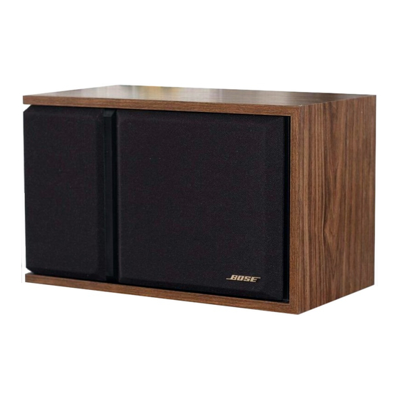
301
SERIES III DIRECT/REFLECTING
Transducers:
1-8"(20 cm) woofer
2-3"(7.6 cm) tweeters
Nominal Impedance:
8 Ohms
IEC Power Rating:
Min: 10 Watts Per Channel
Max: 75 Watts Per Channel
SPECIFICATIONS
Cabinet:
Black, white, or walnut-grained finish
Speaker Dimensions:
10.5"H x 17"W x 9.5" D
(27 H x 43 W x 24 D cm)
Shipping Weight
34 lbs. (15.5 kg) Per Pair
®
SPEAKER SYSTEM
Service Manual
Advertisement
Table of Contents

Related Manuals for Bose 301 Series III


Summary of Contents for Bose 301 Series III
- Page 1 ® ® SERIES III DIRECT/REFLECTING SPEAKER SYSTEM SPECIFICATIONS Transducers: Cabinet: 1-8"(20 cm) woofer Black, white, or walnut-grained finish 2-3"(7.6 cm) tweeters Nominal Impedance: Speaker Dimensions: 8 Ohms 10.5"H x 17"W x 9.5" D (27 H x 43 W x 24 D cm) IEC Power Rating: Shipping Weight Min: 10 Watts Per Channel...
- Page 2 ® BOSE 301 ™ SERIES III TECHNICAL DESCRIPTION The BOSE 301 Series III System is an economical way to enjoy the legendary spatial ® realism of a Direct/Reflecting system. This system creates a natural balance of reflected and direct sound that conventional speaker designs can’t match. The result is lifelike spaciousness that approaches the realism of a live performance.
- Page 3 Test Connections 301 III Speaker Audio Signal Power Amplifier Generator Input Output Speaker FIGURE 1 NOTE: To distinguish between normal suspension noise and rubs or ticks, displace the cone on the woofer slightly with your fingers. If the noise can be made to go away or get worse, it is a rub or a tick and the woofer should be replaced.
- Page 4 Schematic Diagram FIGURE 2 5. Woofer Phase Test NOTE: Supply voltage should only be momentarily applied to the speaker input terminals to avoid possible damage to the speaker. A. Set a DC power supply to 8 volts. To ensure that the woofer is connected in phase, connect the positive lead of the supply to the positive (+) speaker input terminal and the negative lead to the negative (-) input terminal.
- Page 5 2. Replacing the Tweeters NOTE: The positive terminal of each tweeter is marked with a red dot. A. The upper and lower tweeters are mounted on brackets. Refer to Figure 3. Remove one (1) screw which secures either tweeter to its bracket. Lift the tweeter away from the bracket and cut the wires connected to the tweeter as close to the tweeter terminals as possible.
- Page 6 Main Assembly Part Drawing FIGURE 3...
- Page 7 Carton Parts Drawing FIGURE 4...
- Page 8 301 Series III Parts List (Figure 3) Item Description Part Number Qty. See Note Number Speaker Assy. Grille Assembly-Dark Brown 143767-1 Grille Assembly-Black 143767-3 Grille Assembly-White 143767-4 Nameplate-Gold/Brown Bkgnd. 132545-04 Nameplate-Clear/Black Bkgnd. 132545-01 Trim Strip-Black 143770-1 Grille Clip (Not Illustrated) 120716 Woofer-8"...
- Page 9 Crossover Parts List (Figure 3) Symbol or Description Part Number Qty. See Note Item Number Speaker Assy. Capacitor-Film,5%,50V,3.4µF 106825 Resistor-WW,10%,5W,7.5Ω 125605-7R5 Capacitor-Film,5%,50V,3.7µF 107055 Resistor-WW,10%,5W,6.2Ω 125605-6R2 Capacitor-Film,5%,50V,3.0µF 104130 Resistor-WW,10%,5W,9.1Ω 125605-9R1 Capacitor-Film,5%,50V,2.4µF 104131 Resistor-WW,10%,5W,13.0Ω 125605-130 Mini-Lamp 117805 Foam Tape 118223 Foil Tape 103597 Glass Wool 103075...
- Page 10 301 Series III Parts List (Figure 4) Item Description Part Number Qty. See Note Number Carton Literature Kit (N. America) 143754-1 Literature Kit (Europe) 143754-2 which consists of: Owner's Manual 143755 Polybag 103351 Warranty Card (N. America) 129287 Warranty Card (Europe) 132117 Envelope (N.
- Page 11 NOTES FOR FUTURE REFERENCE...
- Page 12 SPECIFICATIONS AND FEATURES SUBJECT TO CHANGE WITHOUT NOTICE 9/92: REV.0 Bose Corporation The Mountain Framingham, Massachusetts USA 01701 P/N 149358 FOR TECHNICAL ASSISTANCE PARTS ORDERING, CALL 800-367-4008...