Table of Contents
Advertisement
Quick Links
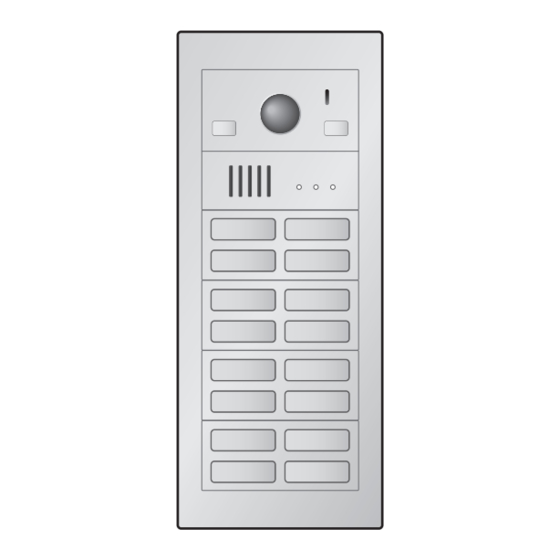
Lobby station
(16 call buttons)
Thank you for purchasing a Panasonic product.
Please follow all instructions in this document and save it for future reference.
Carefully read the information found in the section titled "2.1 Important safety information" in particular.
*1 In India, VL-VM701 is not sold and bus wiring is not available.
This system is an auxiliary system; it is not designed to provide complete protection from property loss.
Panasonic will not be held responsible in the event that property loss occurs while this system is in operation.
Note to the installer
R This document includes instructions for both installation and operation. See the section titled
"4 Installation" for installation instructions.
R Please read this document carefully, and install the product safely and correctly by following the
instructions.
R Only use attachments/accessories specified by the manufacturer.
R The installation shall be carried out in accordance with all applicable installation rules.
Installation and Operating Instructions
Video Intercom System — Lobby station/Distributor
Model No.
VL-VM series / VL-VM701
Lobby station
(8 call buttons)
Distributor
*1
(VL-VM701)
Advertisement
Table of Contents

Related Manuals for Panasonic VL-VM701


Summary of Contents for Panasonic VL-VM701
- Page 1 This system is an auxiliary system; it is not designed to provide complete protection from property loss. Panasonic will not be held responsible in the event that property loss occurs while this system is in operation. Note to the installer R This document includes instructions for both installation and operation.
-
Page 2: Table Of Contents
Table of Contents 1. Introduction System overview ...........3 2. Important Information Important safety information ......7 Important safety instructions ......8 Privacy and rights of portrait ......8 Disclaimer .............8 Other important information ......8 General information ........8 For India only ..........9 For Europe ............9 3. -
Page 3: Introduction
1. Introduction 1.1 System overview This document explains how to install and configure a Video Intercom System for Apartment Complexes comprised 1. . Introduction of the VL-VM series devices. Additionally, general information is provided for connecting other devices to the system. 1.1.1 Main features Easy installation –... - Page 4 1. Introduction 1.1.2 System configuration Star wiring example Example: 32 call buttons on the lobby station Bus wiring example Example 1: 16 call buttons on the lobby station...
- Page 5 The number of required power supply units differs depending on the number of devices used. The number of required power supply units differs depending on the Power supply unit (VL-PS2410) number of devices used. Distributor (VL-VM701) – Up to 8 Extension box (VL-V703) –...
- Page 6 1. Introduction 1.1.3 Lobby station components The lobby station is composed of the following modules according to the number of rooms. See page 26 for information about assembly. Note: R Regardless of the number of button module combinations, a maximum of 8 button modules can be used in 1 lobby station.
-
Page 7: Important Information
2. Important Information R Do not push any objects through the openings of the 2.1 Important safety information product. R If any of the following conditions occur, disconnect To prevent severe injury or loss of life or property, and to the power supply unit from the power outlet, and then 2. -
Page 8: Important Safety Instructions
R If you stop using the product, remove it from the walls to prevent it from falling off. R When power fails, this product cannot be used. R Panasonic may not be liable for damages due to external factors such as power failures. This symbol (A) on the products, packaging, and/or 2.6 General information... -
Page 9: For India Only
For the purpose of recycling to facilitate effective utilization of resources, please return this product to a nearby authorized collection centre, registered dismantler or recycler, or Panasonic service centre when disposing of this product. Please see the Panasonic website for further information on collection centres, etc., or call the toll-free number... -
Page 10: Preparation
3.1 System devices Item Quantity The following modules or devices are sold separately. 3. . Preparation Please contact your nearest Panasonic dealer for sales 1-button module information. Compatible system devices (as of July 2018) 3.1.1 Lobby station The lobby station is composed of combinations of Flat cable modules. - Page 11 3. Preparation VL-VM302 VL-VM303 Item Quantity Item Quantity 2-button module 3-button module Flat cable Flat cable Used to connect modules. Used to connect modules. 2-pin terminal block 2-pin terminal block Used when using star wiring. Used when using star wiring. Spare button Spare button Used as a spare when replacing...
- Page 12 3. Preparation VL-VM304 VL-VM801 Item Quantity Item Quantity 4-button module Extension cable Used to connect 2 frames of a lobby station together. Flat cable Used to connect modules. VL-VM902 (for France) Item Quantity 2-pin terminal block Used when using star wiring. VIGIK panel Spare button Used to prevent the removal of...
- Page 13 3. Preparation Item Quantity Item Quantity Side plate Frame Used to secure and attach the left Used to assemble modules. and right sides of modules. Screw (3 mm ´ 5 mm) Used to attach modules to side plates. Side plate Upper/lower plate Used to secure and attach the left Used to attach the back box to a...
- Page 14 3. Preparation VL-VM502 (small type) VL-VM503 (large type) Item Quantity Item Quantity Surface mount cover Surface mount cover Bracket Used to attach the surface mount cover to the back box. Bracket Used to attach the surface mount cover to the back box. Hex screw (3 mm ´...
- Page 15 3. Preparation 3.1.2 Distributor 3.1.3 Power supply unit VL-VM701 (bus wiring) VL-PS240 (0.6 A type) Item Quantity Item Quantity Distributor Power supply unit Screw (4 mm ´ 40 mm) Screw (3.8 mm ´ 20 mm) Used to secure the power supply Used to secure the distributor to unit to the wall.
-
Page 16: Device Diagrams
3. Preparation A Lens cover 3.2 Device diagrams B Light C Speaker 3.2.1 Lobby station D Call buttons Illuminates in dark environments depending on Front view the DIP switch settings (page 40). Example: 12 call buttons on lobby station E Microphone F Unlock indicator ( ;... - Page 17 3. Preparation 3.2.2 Distributor Example: distributor with the cable cover removed A Connection terminals (output) for next distributor B Connection terminals (input) for lobby station, extension box or previous distributor C DIP switches for distributor ID setting See page 41. D DC IN connection terminals for power supply Used to connect the distributor to the power supply unit.
-
Page 18: Specifications
VL-MVN511, VL-MWD272, VL-MWD273, VL-MV71, Vertically: approx. 110° VL-MV72): up to 32 Minimum 1 lx (within approx. 50 cm from R Distributor (VL-VM701): up to 8 illuminance the camera lens) R Extension box (VL-V703): up to 1 required Lobby station (VL-VM series; sold separately) - Page 19 3. Preparation Distributor (VL-VM701; sold separately) Power supply unit (VL-PS240; sold separately) The distributor is for indoor use only. The power supply unit is for indoor use only. Power source Power supply unit Power source Input: 220–240 V AC, 0.2 A, 50/60 Hz VL-PS240: 24 V DC, 0.6 A...
-
Page 20: Installation Cautions
4. Installation 4.1 Installation cautions 4.2 Installing the power supply unit (sold separately) Refer to the information found in 2 Important Information 4. . Installation (page 7) before installing the product. Required items – Power supply unit (VL-PS240 or VL-PS2410; sold CAUTION separately) –... - Page 21 4. Installation wire should be connected to, and insert the DC 4.2.1 Connecting the AC wires and DC wires wires as shown. (VL-PS240) Strip the ends of the wires that connect to the power CAUTION supply unit as shown below. AC wires DC wires R Insert the power cables firmly all the way into the...
- Page 22 4. Installation wire should be connected to, and insert the DC 4.2.2 Connecting the AC wires and DC wires wires as shown. (VL-PS2410) Strip the ends of the wires that connect to the power CAUTION supply unit as shown below. AC wires DC wires R Insert the power cables firmly all the way into the...
- Page 23 In order to start up distributors (( ); maximum of 8) that use bus wiring, use either the VL-PS240 or VL-PS2410 power supply units in one of the following arrangements. n Number of operable VL-VM701 (distributors) Number of connectable distributors With VL-MV10 main monitor...
- Page 24 4. Installation Example: when a VL-MV10 is connected using 2 VL-PS2410 power supply units The system consists of 2 VL-PS2410 power supply units. 4.2.4 Mounting on a DIN rail Attach the power supply unit to the DIN rail so that the bottom hook is positioned at the bottom of the power supply unit.
-
Page 25: Installing The Lobby Station
4. Installation 4.3.1 Installation position of the lobby station 4.3 Installing the lobby station and camera range Required items Refer to the following examples and confirm the area – Module parts kit (sold separately) with lobby station viewable by the camera. In each illustration, the viewable assembly area is indicated by "A"... - Page 26 4. Installation 4.3.2 Assembling lobby station modules 4.3.3 Connecting flat cables The lobby station is composed of a combination of Remove each terminal cover (A) from each module modules according to the number of rooms connected (A-1). R Remove the terminal cover of the attached –...
- Page 27 4. Installation 1. Remove the waterproof rubber from the panel, and 4.3.4 Connecting 2 frames of a lobby station then remove the screws (A) on the left and right side using the extension cable of the module and panel. When connecting 2 frames of a lobby station together, connect them using the VL-VM801 extension cable (sold separately;...
- Page 28 4. Installation 4.3.6 Installing the lobby station to a wall VL-VM602 (small type: back box) Front view Side view The following 2 methods can be used for installing the lobby station. – flush mounting using the back box (sold separately) –...
- Page 29 4. Installation Installing 2 frames of a lobby station 4.3.7 Flush mounting using the back box When connecting 2 frames of a lobby station together, Open the knockout holes of the back box and pass use the extension cable (sold separately) and install to cables through them.
- Page 30 4. Installation Connect the wires and cables to the lobby station. 4.3.8 Surface mounting using the back box R See "4.6.2 Wire type and maximum wire length and surface mount cover (Page 39)". Open the knockout holes of the back box and pass Attach the lobby station to the back box, and then use cables through them.
- Page 31 4. Installation After securing the surface mount cover to the back Installing 2 frames of a lobby station box, caulk the top and side of the surface mount When connecting 2 frames of a lobby station together, cover with water-resistant sealant. Do not caulk the use the extension cable (sold separately) and install to bottom side.
- Page 32 4. Installation Camera module 4.3.9 Connecting the wires Important: R Make sure you turn off the power to all devices at the breaker before performing any wiring work. Failure to observe this may cause product failure. Remove the terminal cover from the camera module. 7 mm Strip the wires from all devices as below.
- Page 33 4. Installation When using bus wiring: When using bus wiring and VL-VM701 distributor: Insert the wires from the distributor or the extension box into the 6-pin terminal block, tighten the terminal Make the following connections for the distributor. block screws, and then attach the terminal block to a.
-
Page 34: Installing The Extension Box (Sold Separately)
– Specifications – Mounting on a DIN rail or attaching directly to a wall Download the documentation on the Web site below. 7 mm https://panasonic.net/cns/pcc/support/intercom/ 7 mm v900 A DC wires from power supply unit B Wires from lobby station, extension box, or... -
Page 35: Installing The Distributor (Sold Separately)
See 4.6.2 Wire type and maximum wire length (Page 39). Note: R For more information about connections for the VL-VM701 distributor, refer to step 10 on page 33. Installation methods The following 2 methods can be used for installation. – mounting on a DIN rail (user supplied) –... -
Page 36: Wiring Connections
4. Installation 4.6 Wiring Connections 4.6.1 Wiring schematics Note: R See page 23 for information about connections for power supply units. R See page 40 for information about lobby station DIP switch settings. R See page 41 for information about distributor DIP switches when using bus wiring. R Insert the wires fully into the connection terminals. - Page 37 4. Installation Bus wiring examples Maximum number of devices R Lobby station: up to 6 R Main monitor: up to 32 (depending on the composition of the lobby station’s modules) R Distributor: up to 8 R Extension box: up to 1 (required when expanding the lobby stations) Using the distributor Important: R When using bus wiring, do not connect wires from main monitors to the terminals on the rear of the lobby...
- Page 38 4. Installation Using the extension box and distributor Important: R When using bus wiring, do not connect wires from main monitors to the terminals on the rear of the lobby station's button modules. R When connecting to an extension box: –...
- Page 39 4. Installation 4.6.2 Wire type and maximum wire length Wiring run Wire diameter Max. length 0.65 mm (22 AWG) approx. 100 m « Lobby station Main monitor 1.2 mm (17 AWG) approx. 200 m 0.65 mm (22 AWG) approx. 10 m Power supply unit «...
-
Page 40: Dip Switch Settings
4. Installation 4.7 DIP switch settings 4.7.1 Lobby station DIP switch settings The following lobby station DIP switch settings are required when installing the lobby station. DIP SW 1 2 3 4 5 6 7 8 Item Setting DIP switch Item Setting DIP switch... - Page 41 4. Installation 4.7.2 Distributor DIP switch settings The following DIP switch settings are required when installing the distributor using bus wiring. – Distributor ID settings #1 – #8: applicable DIP switches (A) must be configured at each distributor. – Room number ID settings A – f: applicable DIP switches (B) must be configured according to each button number of the lobby stations and rooms.
- Page 42 4. Installation Room number ID settings B Setting DIP switch Setting DIP switch Button A Button Q 1 2 3 4 5 6 7 8 1 2 3 4 5 6 7 8 Button B Button R 1 2 3 4 5 6 7 8 1 2 3 4 5 6 7 8 Button C Button S...
-
Page 43: Distributor Power And Access Indicators
4. Installation 4.8 Distributor POWER and ACCESS indicators You can use the POWER and ACCESS indicators to check the status of devices. R All distributors lit in green indicate that there is no problem. R A red flashing indicator indicates that there is an error. Category Meaning POWER (green) -
Page 44: Room Name Plates
4. Installation 4.10 Room name plates The room name plates of the lobby station can be attached in the follow ways. – Attached so that room name plates can be easily attached and removed in order to change the names of residents. –... -
Page 45: Basic Operations
5. Basic Operations 5.1 System conditions and limitations Please note the following system conditions and limitations. 5. . Basic Operations R Only one call or monitoring session can be handled at a time. – If the call button for the same lobby station is pressed multiple times, the last call button pressed has priority. –... -
Page 46: Other Information
6.1 Basic troubleshooting For advanced troubleshooting, refer the information on the following web site. 6. . Other information https://panasonic.net/cns/pcc/support/intercom/vl-vm If the system does not operate correctly, particularly after installing or modifying the system, first check the following points. R Power is supplied to each device... -
Page 47: Cleaning
6. Other information 6.2 Cleaning Wipe the product with a soft, dry cloth. R For excessive dirt, wipe the product with a slightly damp cloth. R When the product is installed near ocean coasts, wipe the product with a slightly damp cloth once every 2 to 3 months. - Page 48 1006, Oaza Kadoma, Kadoma-shi, Osaka 571-8501, Japan http://www.panasonic.com © Panasonic Corporation 2018 PNQP1382ZA C0718MG0...