Table of Contents
Advertisement
Quick Links
CH 1
GAIN REDUCTION dB
30
24
18 12
6
4
2
1
HIGH
RELEASE
TRIGGER
ATTACK
HOLD
RANGE
+4
20
.25
1
1
4 CHANNEL
.1
KHz
10
GATE
-50
+20
.3
300
.01
4
.02
5
1
80
dBu
mSec
Sec
Sec
dB
30
Hz
3K
LOW
KEY LISTEN
DUCKER
KEY
CH 2
CH 3
LINK
GAIN REDUCTION dB
30
24
18 12
6
4
2
1
HIGH
HIGH
RELEASE
IN/OUT
TRIGGER
ATTACK
HOLD
RANGE
40
+4
20
.5
1
1
40
.1
KHz
10
.1
KHz
10
-50
+20
.3
300
.01
4
.02
5
1
80
dBu
mSec
Sec
Sec
dB
30
Hz
3K
30
Hz
3K
LOW
LOW
IN/OUT
KEY
KEY LISTEN
DUCKER
4 CHANNEL GATE
CH 4
GAIN REDUCTION dB
LINK
30
24
18 12
6
4
2
1
HIGH
RELEASE
TRIGGER
ATTACK
HOLD
RANGE
IN/OUT
TRIGGER
+4
20
.5
1
1
40
+4
20
.1
KHz
10
-50
+20
.3
300
.01
4
.02
5
1
80
-50
+20
dBu
mSec
Sec
Sec
dB
dBu
30
Hz
3K
LOW
KEY
KEY LISTEN
DUCKER
IN/OUT
KEY
GAIN REDUCTION dB
30
24
18 12
6
4
2
1
POWER
RELEASE
ATTACK
HOLD
RANGE
.5
1
1
40
.3
300
.01
4
.02
5
1
80
mSec
Sec
Sec
dB
KEY LISTEN
DUCKER
Advertisement
Table of Contents

Related Manuals for Samson S-Gate 4


Summary of Contents for Samson S-Gate 4
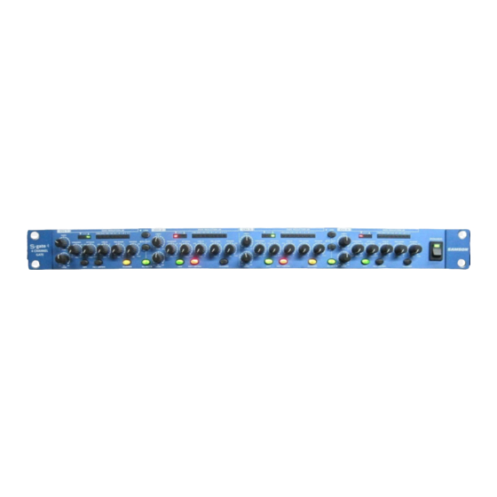
- Page 1 CH 1 CH 2 GAIN REDUCTION dB LINK 18 12 HIGH HIGH RELEASE TRIGGER ATTACK HOLD RANGE IN/OUT TRIGGER 4 CHANNEL GATE mSec KEY LISTEN DUCKER IN/OUT 4 CHANNEL GATE CH 3 GAIN REDUCTION dB GAIN REDUCTION dB LINK 18 12 18 12 HIGH RELEASE...
-
Page 2: Safety Instructions
Caution: To reduce the hazard of electrical shock, do not remove cover or back. No user serviceable parts inside. Please refer all servicing to qualified personnel. WAR NING DO NOT EXPOSE THIS EQUIPMENT TO RAIN OR MOISTURE AV IS RISQUE DE C HO C E LE C TRONIQUE NE PAS OU V RIR WARNING: To reduce the risk of fire or electric shock, do not expose this unit to rain or moisture. - Page 3 Using The Ducker Dynamics Processing 101 Applications System Set-ups S gate 4 Connections Block Diagrahm Specifications Copyright 2001, Samson Technologies Corp. Printed October, 2001 Samson Technologies Corp. 575 Underhill Blvd. P.O. Box 9031 Syosset, NY 11791-9031 Phone: 1-800-3-SAMSON (1-800-372-6766) Fax: 516-364-3888 www.samsontech.com...
- Page 4 Introduction Congratulations on your purchase of the Samson S Gate 4! The S Gate 4 is a four channel Expander/Noise Gate with frequency sensitive triggering, offering unparalleled control and sonic transparency impressing the most critical listeners. Never before have so many features been packed into a single rack space unit with four noise gates - period.
- Page 5 KEY LISTEN DUCKER IN/OUT The Samson S gate 4 dynamics processor utilizes the latest technology in gain management design. Here are some of its main features: • Full featured, four channel Noise Gate with Expander and Ducker on each channel in a sin- glespace, 19"...
-
Page 6: Rear Panel Layout
S gate 4 Front Panel Layout CH 1 HIGH 4 CHANNEL EXPANDER GATE HIGH FILTER CONTROL - Used to set the upper fre- quency at which the 12dB cut is applied to the side chain input, covering a range from .1 to 10 KHz. GATE OPEN &... - Page 7 CH 3 GAIN REDUCTION dB 24 18 HIGH TRIGGER ATTACK HOLD mSec KEY LISTEN 14 KEY SWITCH –When engaged the Key insert is enabled allow- ing the trigger signal to be externally processed or externally controlled. 15 ATTACK - Adjusts the amount of time,from .3 to 300 milisec- onds,that the Gate/Ducker takes to become fully open.
- Page 8 Operating The S gate 4 Whether you are an experienced audio engineer, just starting out, or you just want to experiment, follow the steps below to get going. Further sections in this manual will cover basic dynamics and the associated parameters, sys- tem set-ups and applications for using dynamics processing in recording and live sound applications.
-
Page 9: Gating A Signal
GATING A SIGNAL Unwanted noises, buzzes and hisses can be easily removed by using S gate 4. The idea is to have the Gate open only when the sound you want to hear is playing and to mute off and eliminate (Gate closed) the unwanted noises, buzzes and hisses. -
Page 10: Using The Filters
Operating The S gate 4 USING THE FILTERS The S gate 4 employs a DFT (Dual Filter Trigger) circuit which allows you to create an equalization contour on the trigger filter. The DTF is a two-stage, band-pass equalizer on the trigger or side-chain input. The filters are applied to the trigger whether it is derived from the audio input, or by the KEY input. -
Page 11: Using The Ducker
USING THE DUCKER S gate 4ʼs Ducker feature is a powerful tool for automatically mixing different sound sources. You can use the S gate 4ʼs Ducker when you want one signal to control the level of another channel or channels. One of the most popular examples of using a ducker is when you have a voice-over turn down a music program track. -
Page 12: Dynamics Processing 101
Dynamics Processing 101 To begin to understand dynamics processing, we must first understand what dynamics are. Dynamics, or the dynamic range of a signal or audio device, is the amount of level between the softest and loudest possible out- put. Dynamics processing is applied to a signal to manage the changes in level. Various types of processing units are available to control dynamics including Noise Gates, Expanders, Compressors, Limiters and De-Essers. - Page 13 Dynamics Processing 101 - Continued Soft-Knee / Hard-Knee In order to prevent harsh, unnatural envelopes on compressed signals, sophisticated dynamics processors like the S gate 4 feature an SKD (Smart Knee Detector) or automatic knee circuit. The Smart Knee Detector auto- matically switches from Soft-Knee when the signal is less than 10 dB over Threshold, to Hard-Knee when the signal is 10db above Threshold.
- Page 14 Applications Using the Expander/Gate to Remove Hiss and Noise The S gate 4 is an extremely useful tool in reducing the level of unwanted noises. By using the Expander/Gate you can effectively fade the noise into the noise floor or abruptly turn the unwanted signal completely off. Letʼs say you want to reduce the bleed or cross talk that occurs when different instruments are recorded in close proximity to each other.
- Page 15 LIVE SOUND SYSTEM WITH GATES ON INDIVIDUAL CHANNELS CH 4 BALANCED OUTPUT INPUT MIC/LINE 1 Mixer Insert Points LEFT SOLO In this example, the S gate 4 is inserted on the mixer’s first four input channels. CHANNEL 1 S gate 4 System Set-Ups CH 3 CH 2 BALANCED...
- Page 16 S gate 4 System Set-Ups LIVE SOUND SYSTEM WITH GATES ON SUB INSERT POINTS MIC/LINE 1 MIC/LINE 2 MIC/LINE 3 MIC/LINE 4 MIC/LINE 5 LINE LINE LINE LINE LINE INSERT INSERT INSERT INSERT INSERT PEAK PEAK PEAK PEAK PEAK GAIN GAIN GAIN GAIN...
-
Page 17: Insert Points
CONNECTING THE S gate 4 The are several ways to interface the S gate 4 to support a variety of applications. The S gate 4 features servo- balanced inputs and outputs, so connecting balanced and unbalanced signals is possible without any signal loss. The S gate 4 can be used on a single instrument by connecting to a mixer channelʼs insert points, or on an entire mix "in-line"... - Page 18 Block Diagrahm...
-
Page 19: Specifications
System Specifications System Specifications Frequency Response Dynamic range Crosstalk Detector Gate Trigger range Attack Release Hold Range DUCKER Section RANGE Function Switches Link Filter Key Listen Ducker In/Out Meters & LED's Gain Reduction Gate Activity Specifications 20Hz to 20kHz +/ - 0.5 dB 95 dBu, un-weighted, 22 Hz to 22 kHz 0.008 % typ. - Page 20 Specifications Audio Input Audio Input Connectors Impedance Nominal Operating Level Max. Input Level CMRR Audio Output Audio Output Connectors Impedance Max. Output Level Power Supply Power Supply Mains Voltages/selectable Fuse Power Consumption Power inlet Size Dimensions Weight Weight Net Weight Shipping Weight XLR and 1/4"...
-
Page 22: Phone: 1-800-3-Samson
Samson Technologies Corp. 575 Underhill Blvd. P.O. Box 9031 Syosset, NY 11791-9031 Phone: 1-800-3-SAMSON (1-800-372-6766) Fax: 516-364-3888 www.samsontech.com sg4omv2 sg4omv2...