Table of Contents
Advertisement
Quick Links
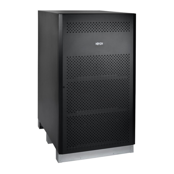
Owner's Manual
Extended-Run
Battery Cabinet
Models: BP480V40, BP480V40-NIB, BP480V65,
BP480V65-NIB, BP480V100, BP480V100-NIB
Not suitable for mobile applications.
Este manual esta disponible en español en la página de Tripp Lite:
www.tripplite.com
Ce manuel est disponible en français sur le site Web de Tripp Lite :
www.tripplite.com
Русскоязычная версия настоящего руководства представлена на
веб-сайте компании Tripp Lite по адресу: www.tripplite.com
Dieses Handbuch ist in deutscher Sprache auf der Tripp Lite-Website verfügbar:
www.tripplite.com
1111 W. 35th Street, Chicago, IL 60609 USA • www.tripplite.com/support
Copyright © 2018 Tripp Lite. All rights reserved.
1
18-05-110-933861-EN.indd 1
7/3/2018 2:58:02 PM
Advertisement
Table of Contents

Related Manuals for Tripp Lite BP480V40


Summary of Contents for Tripp Lite BP480V40
- Page 1 Not suitable for mobile applications. Este manual esta disponible en español en la página de Tripp Lite: www.tripplite.com Ce manuel est disponible en français sur le site Web de Tripp Lite : www.tripplite.com Русскоязычная версия настоящего руководства представлена на веб-сайте компании Tripp Lite по адресу: www.tripplite.com Dieses Handbuch ist in deutscher Sprache auf der Tripp Lite-Website verfügbar:...
-
Page 2: Table Of Contents
5. Maintenance 5.1 Maintenance Schedule 5.1.1 Quarterly Check 6. Mechanical Data 6.1 Physical Measurements 6.1.1 BP480V40/NIB Measurements 6.1.2 BP480V65/NIB and BP480V100/NIB Measurements 6.2 Battery Requirements 6.2.1 BP480V40/NIB Battery 6.2.2 BP480V65/NIB Battery 6.1.3 BP480V100/NIB Battery 14 18-05-110-933861-EN.indd 2 7/3/2018 2:58:02 PM... -
Page 3: Introduction
1. Introduction Tripp Lite’s Extended-Run Battery Cabinets connect to SmartOnline® UPS Systems to provide long-lasting battery backup for data centers, telecommunications, networks, industrial facilities, security, emergency systems and other mission-critical applications that require high capacity, high availability and extended runtime. -
Page 4: Important Safety
2. Important Safety Instructions SAVE THESE INSTRUCTIONS All sections of this manual contain instructions and warnings that must be followed during the installation and operation of the battery cabinet described in this manual. Read ALL instructions thoroughly before attempting to move, install or connect your battery cabinet. -
Page 5: Battery Warnings
Do not lay tools or metal parts on top of batteries. • Replace batteries with equivalent batteries (same number and type) available from Tripp Lite. • The batteries are recyclable. Refer to local codes for disposal requirements. Do not dispose of batteries except through approved channels in accordance with all applicable local, state and national regulations. - Page 6 • Allow batteries to charge uninterrupted for 24 hours after installation. • Do not attempt to service the integrated battery charger (included with “C” models only). Contact Tripp Lite if service is required. Note on Labeling These symbols may appear on the product label:...
-
Page 7: Battery Cabinet Installation
If you determine the unit has been damaged during shipping or if anything appears to be missing, contact Tripp Lite for assistance. Do not attempt to use the unit if it has been damaged or mishandled. -
Page 8: Internal Wiring (Typical)
3. Battery Cabinet Installation 3.4 Internal Wiring (Typical) • Battery cabinets use multiple 12V DC batteries connected in series to provide nominal DC voltage of 480V DC (±240V DC). • Internal cabling is sized for specific application load currents. Do not use any other cable size other than the one provided in the battery cabinet. -
Page 9: Electrical Connection
3. Battery Cabinet Installation 5. Forklift forks should be at maximum width within the cabinet clearance opening and fully inserted to prevent tipping. Lift cabinet from bottom only. Be careful not to damage the sheet metal floor of the cabinet with the forks. 6. -
Page 10: Final Electrical Check
3. Battery Cabinet Installation 7. Feed the positive and negative cables (and “N” center, if equipped) from the open external disconnect switch or the UPS battery field wiring terminals through the conduit/cable bushing. Connect to the respective output terminals inside the battery cabinet. 3.8 Final Electrical Check Before closing any connecting circuit breaker or disconnect switch, complete these verification steps:... -
Page 11: Operation And Charging
4. Operation and Charging 4.1 Determine Charging Voltages Your Tripp Lite UPS is already set up for proper float and boost voltages from the factory. 4.2 Initial Charge Proper amp-hour rating and charge current must be manually input into the UPS setup. Refer to the Tripp Lite UPS Owner’s Manual for details. -
Page 12: Mechanical Data
6. Mechanical Data 6.1 Physical Measurements 6.1.1 BP480V40/NIB Measurements Dimensions (H x W x D): 1220 x 626 x 900 mm Empty Cabinet Weight: 103.3 kg TOP VIEW BREAKER FRONT VIEW SIDE VIEW REAR VIEW 18-05-110-933861-EN.indd 12 7/3/2018 2:58:03 PM... -
Page 13: Bp480V65/Nib And Bp480V100/Nib Measurements
6. Mechanical Data 6.1.2 BP480V65/NIB and BP480V100/NIB Measurements Dimensions (H x W x D): 1500 x 826 x 1135 mm Empty Cabinet Weight: 157.6 kg (BP480V65/NIB model) 157.6 kg (BP480V100/NIB model) TOP VIEW BREAKER FRONT VIEW SIDE VIEW REAR VIEW 18-05-110-933861-EN.indd 13 7/3/2018 2:58:03 PM... -
Page 14: Battery Requirements
6. Mechanical Data 6.2 Battery Requirements 6.2.1 BP480V40/NIB Battery Lead-Acid Cell Type and Quantity: 12V 40Ah x 40 Batteries Lead-Acid Battery Maximum Size (H x W x L): 170 x 165 x 197 mm Terminal Type: M6 Bolt Terminal Torque (applies to CSB GP 12400 model): 59 kgf•cm/5.73 N•m... -
Page 15: Installation
The “F” marks the front side of the battery cabinet; the “R” marks the rear side of battery cabinet. Battery shelf structure: The cabinet includes four trays total from L1 (bottom) to L4 (top). BP480V40/NIB BP480V65/NIB AND B480V100/NIB 18-05-110-933861-EN.indd 15 7/3/2018 2:58:04 PM... -
Page 16: Cable Jumpers And
CABLE CABLE ITEM DESCRIPTION UNIT LENGTH QUANTITY NUMBER BP480V40/BP480V40-NIB (40Ah batteries) #1 AWG CABLE (BLACK) #1 AWG CABLE (BLACK) #1 AWG CABLE (BLACK) #1 AWG CABLE (BLACK) BAT + #1 AWG CABLE (BLACK) #1 AWG CABLE (BLACK) #1 AWG CABLE (BLACK) -
Page 17: Installing Cable Jumpers
7. Installation 7.2.2 Installing Cable Jumpers to Battery Terminals The BP480V40/BP480V65/BP480V100 battery cabinets and Tripp Lite batteries include hardware to attach the cable jumpers to the batteries’ positive (+) and negative (-) terminals. Refer to the illustration below for proper hardware installation. -
Page 18: Battery Cabinet Internal Wiring
7. Installation 7.2.3 Battery Cabinet Internal Wiring Input/Output Breaker 200A/250Vdc BP480V40 18-05-110-933861-EN.indd 18 7/3/2018 2:58:04 PM... - Page 19 7. Installation Input/Output Breaker 300A/600Vdc BP480V65 18-05-110-933861-EN.indd 19 7/3/2018 2:58:05 PM...
- Page 20 7. Installation Input/Output Breaker 400A/600Vdc BP480V100 18-05-110-933861-EN.indd 20 7/3/2018 2:58:05 PM...
-
Page 21: Battery Installation
7. Installation 7.3 Battery Installation 1. Pull out the latch from the front door hinge. Remove door. BP480V40/NIB BP480V65/NIB and BP480V100/NIB 18-05-110-933861-EN.indd 21 7/3/2018 2:58:05 PM... - Page 22 7. Installation 2. Unscrew the M4 screws with a Phillips screwdriver and remove the side, top and rear panels. BP480V40/NIB BP480V65/NIB and BP480V100/NIB 18-05-110-933861-EN.indd 22 7/3/2018 2:58:06 PM...
- Page 23 7. Installation 3. Unscrew the M6 screws from each battery tray. Remove all the battery trays from cabinet. BP480V40/NIB BP480V65/NIB and BP480V100/NIB 18-05-110-933861-EN.indd 23 7/3/2018 2:58:06 PM...
- Page 24 (L4). See below right figure for internal wiring “L1”. Reference the table and diagram in section 7.2.1 for the appropriate wire jumper needed. REAR TO L2 + TO BREAKER + BP480V40/NIB FRONT REAR TO L2 + TO BREAKER + BP480V65/NIB...
- Page 25 7. Installation 5. Use the saved M6 screws to secure the battery tray for L2. BP480V40/NIB BP480V65/NIB and BP480V100/NIB 18-05-110-933861-EN.indd 25 7/3/2018 2:58:07 PM...
- Page 26 6. See the below right diagram for internal wiring “L2”. Reference the table and diagram in section 7.2.1 for the appropriate wire jumper needed. REAR TO BREAKER N TO L1 – BP480V40/NIB FRONT REAR TO L1 – TO BREAKER N...
- Page 27 7. Installation 7. Use the saved M6 screws to secure the next battery tray for L3. BP480V40/NIB BP480V65/NIB and BP480V100/NIB 18-05-110-933861-EN.indd 27 7/3/2018 2:58:08 PM...
- Page 28 8. See the below right diagram for internal wiring “L3”. Reference the table and diagram in section 7.2.1 for the appropriate wire jumper needed. REAR TO BREAKER – TO L4 – BP480V40/NIB FRONT REAR TO BREAKER – TO L4 –...
- Page 29 7. Installation 9. Use the saved M6 screws to secure the next battery tray for L4. BP480V40/NIB BP480V65/NIB and BP480V100/NIB 18-05-110-933861-EN.indd 29 7/3/2018 2:58:09 PM...
- Page 30 10. See the below right diagram for internal wiring “L4”. Reference the table and diagram in section 7.2.1 for the appropriate wire jumper needed. REAR TO BREAKER N TO L3 + BP480V40/NIB FRONT REAR TO BREAKER N TO L3 +...
- Page 31 7. Installation 11. Use the saved M4 screws to reinstall and secure the side, top and rear panels to the battery cabinet frame. BP480V40/NIB BP480V65/NIB and BP480V100/NIB 18-05-110-933861-EN.indd 31 7/3/2018 2:58:10 PM...
- Page 32 7. Installation 12. Reinstall the front door and reinsert the latch to the door hinge. BP480V40/NIB BP480V65/NIB and BP480V100/NIB 18-05-110-933861-EN.indd 32 7/3/2018 2:58:11 PM...
-
Page 33: Installation Specifications
7.4.1 Installation and Floor Loading Information Battery Dimensions Cabinet Model Shelves (Height x Width x Depth) Casters Weight Floor Load BP480V40 1220 x 626 x 900 mm 607.8 kg 1080 kg/m BP480V40NIB 1220 x 626 x 900 mm 103.3 kg 184 kg/m... -
Page 34: Storage And Service
Failure to recharge the batteries periodically may cause irreversible battery damage. Service Your Tripp Lite product is covered by the warranty described in this manual. A variety of Extended Warranty and On-Site Service Programs are also available from Tripp Lite. For more information on service, visit www.tripplite.com/support. -
Page 35: Warranty
Seller will repair or replace the product, in its sole discretion. Service under this Warranty includes parts and Tripp Lite service center labor. On-site service plans are available from Tripp Lite through authorized service partners (in most areas). Visit www.tripplite.com/support for details. International customers should contact Tripp Lite support at intlservice@tripplite.com. - Page 36 1111 W. 35th Street, Chicago, IL 60609 USA • www.tripplite.com/support 18-05-110 93-3861_revA 18-05-110-933861-EN.indd 36 7/3/2018 2:58:11 PM...