Table of Contents
Advertisement
Quick Links
Advertisement
Table of Contents

Related Manuals for Elation E-Node 8


Summary of Contents for Elation E-Node 8
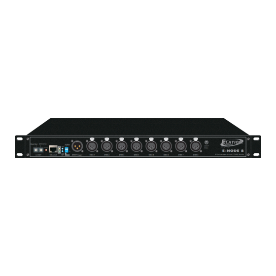
- Page 1 1=Ground 250k 2=Data- 8 Universal DMX System Power 3=Data+ E-NODE 8 1000k Baud 8 U n i v e r s e s A r t n e t / D M X N o d e Ethernet DMX Trigger...
- Page 2 Table of Contents Part I: About E-NODE 8 Part II: X-Soft-Net(Holding System) Operation (1) How to Setup (2) How to Map (3) How to playback preset Scenes by running X-Software & DMX Trigger Operation Incl. (4) X-Net Configure software Operation...
- Page 3 Part I About E-NODE 8...
- Page 4 About 8 Universal DMX System(E-NODE 8) Introduction: Thank you for your purchasing the Elation 8 Universe DMX System(E-NODE 8). To optimize the performance of this product, please read these operating instructions carefully to familiarize yourself with the basic operation E-NODE 8 Universe DMX System been tested at the factory before being shipped to you.
- Page 5 1.Under ArtNet protocol, you MUST firstly set your PC's IP address of "2.16.0.3", and Subnet mask addressing of "255.0.0.0" 2.Under CL100M protocol, the X-Net Configuration software from Elation will be available. You MUST firstly set your PC's IP address of "172.16.0.3", and Sub mask addressing of "255.255.255.0".
- Page 6 IP Address Setting(SW1~3 Operation): Before using the node, please set the existing E-NODE 8's IP addressing from 172.16.0.[0]~172.16.0.[255] by using SW1~SW3 as you desired. As per E-NODE 8, 172.16.0.0, 172.16.0.3, 172.16.0.255 are not available. Set IP: [0~255]= A*100+B*10+C A=0~2 B=0~9...
- Page 7 Part II X-Soft-Net Holding System & Operation Guide...
- Page 8 Configuring your computer Ethernet card before installing To use E-NODE 8 to drive LED lightings from Elation as needed with X-Software software operation. Before using X-Software software, it is advisable to firstly configure your computer Ethernet card. The process is very simple and is described as the below instructions.
- Page 9 Setup Information This is a setup software in the X-Software which is used to set all information as needed. It features mainly; To set Node IP Address To edit/Create Events(trigger time setup) Events(Flash files-*swf, *GVI, Video Files-*AVI,*WMV, MPEG Files-*mpeg,*mpg,*mlv, *mp2,*mp3) Backup/Load Create GVI DMX Control Mode Setup...
- Page 10 1a. Click the ''Show IP set Form'' icon, a IP setup dialog box will bring up to add IP address of nodes which will be used as needed. 1b. Enter a valid integer value of node quantity which will be used as needed in the entire system. Node quantity IP address of each node 1c.
- Page 11 Section_2: Events Editing/Creating(Events Trigger Time Setup) 2a. Events Edit/Create mode enables. All events(Flash files, Video Files, MPEG Files) which have been copied to the "Scene_lib" folder will automatically be listed and display in the Source Components Presentation List. Calendar Source Components Presentation List PC time(real-time clock) Start Time...
- Page 12 2g. Clicking the "Display Events" icon allows the user to preview these events which have been completed, and they will appear with individual start time and end time in the destination component list. All events(Flash files, Video Files, MPAG Files) which have been edited completely will be listed and appear with individual start time and end time in the Destination Components Presentation List.
- Page 13 2.1.Firstly, select the "Scene_lib" folder as a destination which the user load more Flash files, Video Files, MPEG Files to, and click the "Load File" icon. 2.2 Define the folder with more Flash files, Video Files, MPEG Files which you wish to load, then secondly click the "load File"...
- Page 14 4a. Select one Event(Flash files, Video Files, MPEG Files) in the Source Component Presentation List, and click the "Add" icon for dummy GVI. 4b. To repeat the above step to add more events for dummy GVI as needed. In this option, click the "Insert" icon to insert events between two events as needed. Click the "DEL"...
- Page 15 Section_4: DMX Control Mode Setup In this mode, all scenes/Events(Flash files, Video Files, MPEG Files) are available to be controlled and playback by addressing DMX address. And user may use DMX values to control the desired scenes. For further information, please refer to the accompanying table: DMX Trigger function available Preview Area...
- Page 16 After creating a map in X-Mapping, allows it to download and store in your computer. Configure the Art-net devices parameters as needed, i.e. E-NODE 8 from Elation (For further information, please refer to their accompanying manual). Creating LED mapping patterns for use with X-software operation. 2. Installation To install the X-Mapping program, simply double-click on the ''SETUP.EXE'' file and follow its installation...
- Page 17 (If you just want to use four E-NODE 8, you MUST NOTE: For conveniently working, all nodes enter "4" in the blank.) have been added and set up by default.
- Page 18 5. Customizing Dummy Devices In the Edit/Add... option, it allows the user to choose, create or modify devices library list as needed Device Select is a drop down menu that displays existing device or Edit/Add option. Click the "Edit/Add" icon, a new dialog will show as following; Fixture Library List Adds a new dummy device Modifies an existing device which...
- Page 19 Total Pixels show the device pixels's information. After clicking , You can save your existing settings. And created device will be existing in the device library list. 5.2. If you're not satisfied these created devices's setting, or something else wrong happens, it allows the user to modify these settings.
- Page 20 6. Create a Pixel Map After all devices and fixtures settings are finished, access to built a pixel map as needed. Toolbar Existing Device Info Tab Device Select is a drop down menu that displays existing device which you wish to assign the device to the Pixel Map.
- Page 21 HINT: In the event of some mistakes happen, user can modify them by pointing the device number with the mouse action. A new dialog box will display and enter a correct number, then click the ''OK'' icon to save. You MUST ensure overall pixels array order is matching with their scanning order which has been set up.
- Page 22 6.9. After you're satisfied with overall settings, you can click the ''Convert Map Address'' icon to convert the pixel map addresses. Program Rate 6.10.and click the '' Save( )'' icon in the Toolbar save in the main folder as a LEDMap file for X-Software operation.
- Page 23 How to playback preset Scenes by running X-Software? Starting X-Software In the main folder, click the "Runproj"( ) icon to start your X-Software. And the X-Software will display the following screen for you; Presentation Area Tool Bar Dimming Area Using the Tool Bar Manual Mode To manually open the Flash files, Video Files, MPEG Files which you wish to play, firstly click the "MANUAL"...
- Page 24 Dimming Area Operation Node is a drop down menu that displays the actual IP Work Grid features to adjust address of each node. the brightness Outport is a drop down menu that displays the existing outport of the selected Node. Pixel is a drop down menu that displays the existing pixel map address of the selected Outport.
- Page 25 1.4 Select an existing pixel address of the selected outport. In the drop down menu, "Port_pixel_all" means all the pixels existing in selected outport, while "Node_Pixel_all" means all the pixels existing in selected node. 1.5 Adjust the brightness by moving the work grid. For example: A.
- Page 26 ) are available to be controlled and playback by addressing DMX address. And user may use DMX values to control the desired scenes. Before any DMX trigger operation, please ensure all of connections among of your E-NODE 8 and DMX Trigger device(DTC-512 or X-Trigger-USB) with your computer are be connected properly.
- Page 27 2.1 "Fileconvert" icon used to convert the flash file with extension .swf into the file with extension .scn for E-NODE 8 playing the one directly. 2.2 "Preview" icon used to temporarily play flash files effect by E-NODE 8 controlling RGB lightings. NOTE : Before converting flash files, please enter a valid number to set the desired flash frame in the Convert Set Option.
- Page 28 3.4 "Del" icon used to delete pointed files in E-NODE 8. 3.5 "Format" icon used to clear up all files in E-NODE 8. 3.6 "Edit Show" icon used to start and edit the SHOW in E-NODE 8. It is necessary to click the icon for SHOW readout in E-NODE 8.
- Page 29 4.Event Edit Option: In this option, the user can call up Time Trigger Mode for SHOW by editing show events to E-NODE 8, including Weekly Mode, Daily Mode and Date Mode. How to Edit show events? 4.1 To select your desired time trigger modes.