Table of Contents
Advertisement
Advertisement
Table of Contents

Related Manuals for Honeywell POL-200-TS

Summary of Contents for Honeywell POL-200-TS
- Page 1 POL-200-TS User Manual User Manual POL-200-TS ANALOGUE LOOP DIAGNOSTIC TOOL...
- Page 2 POL-200-TS User Manual Safety Information Severe damage Please, before connecting any external cable, make sure the loop cable has been disconnected from the panel loop terminals and the tool is completely powered down. Check for the right terminal connections and make sure there is no external voltage between the cables to be connected.
-
Page 3: Table Of Contents
POL-200-TS User Manual Contents Page EQUIPMENT DESCRIPTION ...........................4 Technical features ..............................6 EC conformity .................................7 PACKAGING CONTENTS ..........................8 EQUIPMENT USE ..............................9 Battery charge ................................9 Connection ................................9 Main menu ................................11 Set language ................................11 Configuration ...............................12 Multimeter ................................13 Loop ..................................14 Sample ..................................17 Map ...................................17 3.10... -
Page 4: Equipment Description
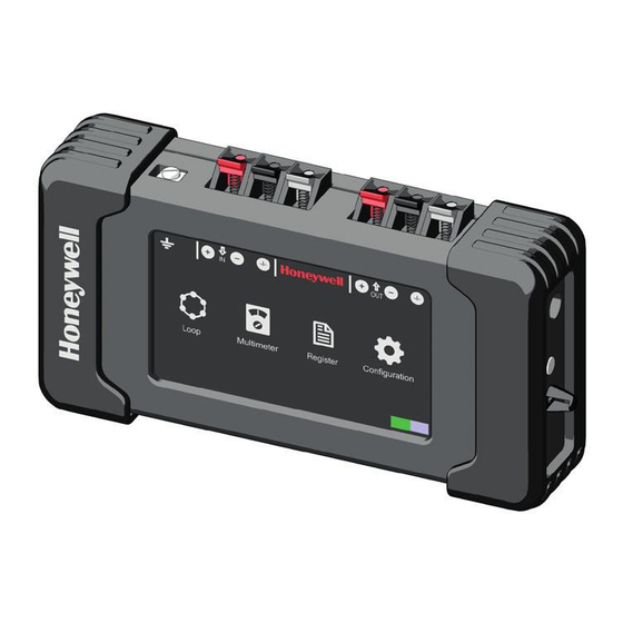
POL-200-TS User Manual 1. Equipment description POL-200-TS is a device with a colour touch screen display. It is used for the preliminary check of the loop device installation compatible with Notifier control units. POL-200-TS can recognize all the loop devices with CLIP/ADVANCED protocols from Notifier, with additional multimeter and oscilloscope functions. - Page 5 POL-200-TS User Manual USB CONNECTOR TYPE B (ref. to par. 3.10) SPRING CONNECTOR TOUCH SCREEN PANEL SUPPLY CONNECTION POWER BUTTON STRAP HOOK...
-
Page 6: Technical Features
Humidity: 65 ± 20% POL-200-TS has an even power-off that can discharge the batteries if it is not used for an extended period of time. If the unit is not used for a long period, we recommend charging the batteries. -
Page 7: Ec Conformity
POL-200-TS User Manual 1.2 EC conformity This document is a declaration that the products listed below conform to the essential protection requirements of the following European Directives: • RoHS - Restrictions on the Use of Certain Hazardous Substances in Electrical and Electronic Equipment •... -
Page 8: Packaging Contents
POL-200-TS User Manual 2. Packaging contents 1 - POL-200-TS 2 - CHARGER 3 - USB CABLE 4 - USB KEY (user manual, device default files) 5 - STRAP... -
Page 9: Equipment Use
POL-200-TS User Manual 3. Equipment use 3.1 Battery charge Use only the original charger provided with the device. Do not charge the appliance at temperatures lower than 0°C or higher than 40°C. Using a universal charger will automati- cally invalidate the guarantee. - Page 10 Shielded/screen cables should only be connected to ground, GND, on one point inside the fire panel. The POL-200-TS allows the user to confirm that the shield is continuous, so it should be approximately twice (2x) and three (3x) times the resistance of the negative conductor. So, in case that the negative conductor has a: •...
-
Page 11: Main Menu
POL-200-TS User Manual 3.3 Main menu When the device is turned on, the HOME screen appears. From this screen it is possible to access all the device functions described in the following paragraphs. Connection indication LOOP icon CONFIGURATION (see par. 3.7) icon (see par. -
Page 12: Configuration
The “About” icon indicates the software ver- sion of POL-200-TS. The “Flash Format” option should only be used if indicated by Honeywell technical department. The “QR” icon allows accessing with a Smart- phone the latest online version of the manual from this web link https://notifier.es/index.php/documentos/... -
Page 13: Multimeter
POL-200-TS User Manual 3.6 Multimeter The Multimeter function can be accessed from the main screen. The multimeter allows the installer to check that the line impedance described in the previous section is correct. After the connection check that POL- 200-TS has the correct load level. -
Page 14: Loop
3.7 Loop The tool recognizes the sensors and modules on the loop before powering the fire alarm control panel (FACP). The POL-200-TS unit is compatible with CLIP (Classic Loop Interface Protocol) with 99 sensors and 99 modules and the new Advanced or Opal protocol with up to 159 sensors and 159 modules. - Page 15 “Notifi- er”, “Morley”, “System Sensor” or “Honeywell HBS”. In case in one address a device changes the type ID or in case of a change from lower case to capital letter, please check the wiring in this device as its answer is not correct.
- Page 16 A “-” character in ID type may indicate a duplicate address. For each sampling POL-200-TS identifies the changes that have occurred since the previous sampling, and the type of ID identifying each address will appear in red or black. The red colour indicates that a change has occurred.
-
Page 17: Sample
If the installer has correctly wired the isolators using the +IN, +OUT terminals in the B501AP or in the module terminals, POL-200-TS will activate the isolator and a graph is displayed. POL-200-TS provides a device map for any of the protocols, CLIP or Advanced. -
Page 18: Event Recording
Once the devices are selected and the “only selected items” register option is selected, POL-200-TS will display the following screen: Record through the configuration option only the necessary information, consult Honey- well’s technical department or, if in doubt, se- lect all the options. - Page 19 POL-200-TS User Manual The maintenance option will create a text file with “.MNT” extension that can be edited with “notepad” or Word for later editing. The USB connector allows the installer to download the loop device maintenance file or to up- date the firmware when a new version is available.
-
Page 20: Battery Replacement
POL-200-TS User Manual 4. Battery replacement The battery life lasts maximum 3 years; after this period and if charge duration shortens, replace batteries. Use 6 AA type, 220 mAh rechargeable batteries Danger of explosion in case of inappropriate battery replacement! Batteries must be disposed of according to the laws in force. -
Page 21: Troubleshooting
Check that you have not selected Advanced protocol instead of CLIP protocol No devices appear: Check that the loop is connected to the input, “IN” of the POL-200-TS device. There is no data recorded in my * .MNA, * .MNC and / or Remove or delete old files, they take up the available memory space. - Page 22 POL-200-TS User Manual Notes...
- Page 23 POL-200-TS User Manual Notes...
- Page 24 Honeywell C/Pau Vila 15-19 08911 Badalona Barcelona, Spain POL-200-TS Diagnostic tool Ref. doc.: MN-DT-963_EN Tel.: 93 497 39 60 Fax: 93 465 86 35 12-17 www.honeywelllifesafety.es © 2017 Honeywell International Inc.