
Related Manuals for Verizon Networkfleet 5500


Summary of Contents for Verizon Networkfleet 5500
- Page 1 Installation Guide Verizon Networkfleet 5000 PRODUCT LINE INSTALLATION GUIDE 5500 Diagnostic Hardware (Light/Medium/Heavy Duty) | 5200 Non-Diagnostic Hardware (Universal)
-
Page 2: Table Of Contents
Table of Contents Getting Started Registration Form ........................... 3 5000 Product Line Unit Overview ..........................4 Harness Options ..........................5 Light/Medium Duty OBD-II Harness Installation ................7 Heavy Duty Harness Installation ....................10 Universal Harness Installation ..................... 11 Quick Install Harness Installation ....................12 Verifying Successful Installation .................... -
Page 3: Registration Form
Registration Form Fill out the enclosed registration form before completing installation. Record the following information: Vehicle Identification Number (VIN) | License Plate | Year | Make | Model Unit’s Serial number (10 digits) Installation Tip: Metal walls and tall buildings may interfere with the reception from GPS satellites and the cellular network. -
Page 4: 5000 Product Line
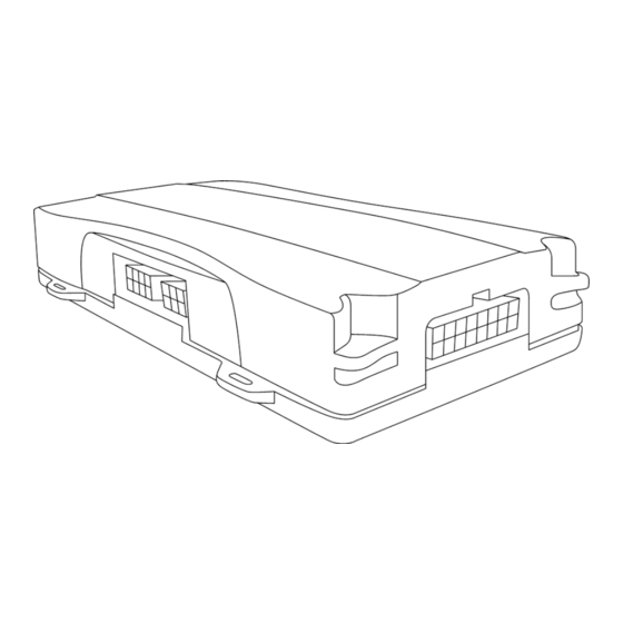
5000 Product Line Unit Overview LED Indicator Lights Side of Unit Note: All 5500 and 5200 units are shipped with a knock-out panel covering the sensor/serial ports. In order to access those ports, you must use an X-ACTO knife to slice off 2 of the 3 tabs in order to remove the knock-out panel. Serial Port Sensor Port Data Port... -
Page 5: Harness Options
Harness Options for the 5000 Product Line Prior to installation, you must select and order the appropriate harness for your vehicle type. The Light/Medium Duty OBD- II Harness and the Heavy Duty Harnesses are compatible with both the 5500 and 5200 hardware devices. Please refer to the list below to verify harness compatibility for each of the 5000 series devices: 5500 (Diagnostic Capable Hardware) •... - Page 6 Heavy Duty Harnesses There are 3 different harness options for Heavy Duty vehicle installations: 6-pin Harness, 9-pin Harness, and 9-pin “D” Harness. 6-pin Harness 9-pin “D” Harness 9-pin Harness...
-
Page 7: Light/Medium Duty Obd-Ii Harness Installation
Light/Medium Duty OBD-II Harness Installation Select an Adapter that most resembles the shape of the OBD-II port of the vehicle. Use these guidelines to match an adapter to the vehicle it is most likely to fit (each adapter is stamped with a number). Note: Ford, GM (1), (6), or (8) For certain Toyota and Chrysler vehicles, you may need to adjust... - Page 8 Light/Medium Duty OBD-II Harness Installation Core Connector Assembly Snap the selected plastic adapter to the back of the Core Connector. Attach the Core Connector to the OBD-II Replacement Connector. Data Port Connection Connect the Harness Connector to the Data Port. OBD-II Replacement Connector...
- Page 9 Light/Medium Duty OBD-II Harness Installation Connecting to the OBD-II Port With the vehicle’s engine OFF, remove the vehicle’s OBD-II port. The OBD-II Connector may be hidden behind a hush panel. To remove the connector, you may need to remove screws or depress the clips. Connect the Bypass Connector to the vehicle’s OBD-II port that was previously removed.
-
Page 10: Heavy Duty Harness Installation
Heavy Duty Harness Installation Connecting to the Diagnostic Link Connector (DLC) Port With the vehicle’s engine OFF, unscrew the DLC port from its position under the dashboard*. In most cases, the DLC port is located under the dashboard on the left side of the steering wheel, facing toward the floorboard. Plug the Bypass Connector of the harness into the DLC port that was previously removed from the vehicle in step 1. -
Page 11: Universal Harness Installation
Universal Harness Installation Note: Please ensure that the Driver Door is OPEN during the ENTIRE installation process. Black Wire (one pair) - Ground • With the vehicle’s engine OFF, attach both the Black Wires directly to a chassis ground point or to a ground line (chassis ground) by splicing directly to a ground lead or by using a poke and wrap method. -
Page 12: Quick Install Harness Installation
Quick Install Harness Installation Open box. Make sure all necessary components are inside for proper install. Harnesses are shipped separately and cannot be returned once opened. Locate the DLC or OBD-II port for installation and plug-in the DLC side of the Quick Install Harness, then plug-in the vehicle harness side of the Quick Install Harness into the Networkfleet device. -
Page 13: Verifying Successful Installation
Verifying Successful Installation Start the vehicle’s engine. All lights (Red, Yellow, and Green) on the device should turn on solid for 15 seconds and then begin blinking rapidly (twice a second). The device is operating normally when the rapid blinking ceases and the Green and Yellow lights begin to blink in a slow pattern (ON for 5 seconds and OFF for 1 second). -
Page 14: Creating Tamper Evidence
Creating Tamper Evidence Once the vehicle harness is plugged in, slide the Networkfleet branded yellow zip ties through the two slots provided on the harness connector. Once the zip ties are in place, tighten and remove the excess plastic. If possible, position the zip ties so that the “DO NOT REMOVE”... -
Page 15: Completing Installation
Completing Installation Before securing the device under the dashboard, make sure that you have recorded the VIN, hardware serial number and odometer reading on the registration form. Also verify that you have checked the light indicators. After installation, provide the registration form to the fleet manager for delivery to Networkfleet or if you are a Networkfleet Certified Installer, please fax to 866.616.2131 or email to installs@networkfleet.com. -
Page 16: Securing The Device
Securing the Device Use zip ties to fasten the hardware securely to a stable bracket or wire bundle under the dash. IMPORTANT: The device must be installed high in the dashboard area and secured with the top of the unit facing the sky (the side of the unit with the Networkfleet logo). Also verify that the device is not covered by metal and check that the green LED is blinking in a slow pattern, which verifies that the unit is getting GPS data (as explained on page 13). -
Page 17: Window-Mount Gps Antenna
Window-Mount GPS Antenna Units are shipped with a knock-out panel covering the sensor/serial ports. First, use an X-ACTO knife to slice off 2 of the 3 tabs in order to remove the knock-out panel. Use enclosed alcohol preparation pad to clean the inside windshield where the antenna is to be placed. For proper operation, the antenna should be placed on flat, clear glass on the driver’s side interior lower corner of the windshield. -
Page 18: Sensor
Sensor The 5500 and 5200 devices include a sensor port for monitoring various voltage events occurring within the vehicle such as: PTO engagement/disengagement, secondary engine on/off, and door open/close. Please review prior to performing sensor installation: • Installer shall use only a digital multi-meter to verify that line Voltage is within the product tolerances. •... - Page 19 To Install Units are shipped with a knock-out panel covering the sensor/serial ports. First, use an X-ACTO knife to slice off 2 of the 3 tabs in order to remove the knock-out panel. Connect the Sensor Input Harness to the Sensor Port on the 5500 or 5200 device. Verify installation by checking the LED behavior of the device (see page 23) and call Customer Care at 866.227.7323 and select Option 5.
-
Page 20: Garmin
® Garmin Networkfleet is ONLY compatible with Garmin devices that support Fleet Management Interface Version 2.6 and higher. The list of compatible units can be found here: www.garmin.com/solutions/pnd/supportedproducts.jsp (look for “Supports Version 2.6 Fleet Management Interface” in the description). All Garmin devices, even if they support Fleet Management Interface Version 2.6, will need a firmware update prior to installation. -
Page 21: Bluetooth Extension Module
Before securing the device under the dashboard, make sure you have recorded the appropriate information on the registration card included with the BTE module. 10. To verify installation, call Verizon Networkfleet Customer Care at 866.227.7323 and select Option 5. Notify your account SSP administrator that vehicle is now eligible for J. J. Keller enrollment. -
Page 22: Port Expansion Module (Pem)
Port Expansion Module (PEM) Note: To enable PEM functionality, the 5000 series device may need an over- the-air firmware update. Customer Care will determine this during the installation verification call. As indicated on page 16, the PEM should NOT be installed over, or covering the top of the Networkfleet unit with the logo. -
Page 23: Quake Satellite Modem
Quake Satellite Modem Note: Installation must be performed in a known good cellular coverage area. The preferred installation method and placement for the Quake satellite modem is mounted with zip ties under the dashboard, near the Networkfleet unit. If there is no room to do this, then the option is to secure the modem elsewhere in the vehicle with zip ties, screws, or strong two- sided tape as necessary Installation Process:... -
Page 24: Verifying Successful Installation/Led Behavior
Verifying Successful Installation/LED Behavior To verify successful installation, call Customer Care at 866.227.7323 and select Option 5. LED Behavior for Sensors: When the Sensor Input Harness is detected by the unit, all LEDs should be turned on solid for 10 seconds. When you engage Sensor 1 (if installed), the yellow LED shall blink rapidly (1/4 second) every time a transition is detected (on to off/off to on). -
Page 25: Pelican Micro Case
Pelican Micro Case Note: The Pelican Micro Case is compatible with the Networkfleet 5200 device and the Universal Harness. Installing the 5200 in the Pelican Micro Case • Slide Universal Harness through the hole in the Pelican Micro Case. • Connect the Harness to the unit and place the unit into the form fitting foam inside the Pelican... -
Page 26: Troubleshooting Light Indicators
Appendix: Troubleshooting Light Indicators Issue: Red light continues to blink rapidly • Solution: Verify that the unit is not surrounded by metal. • Contact Customer Care to confirm network coverage availability and the SIM is active. Issue: Yellow light continues to blink rapidly •... -
Page 27: Frequently Asked Questions
Frequently Asked Questions Are the 5000 series harnesses interchangeable between all other Networkfleet product lines? When installing the 5200 device, are fuses involved or can the device be “wired hot”? We recommend splicing the 5200 harness to fused leads, though the device can be “wired hot” since there is an internal re-settable fuse. -
Page 28: Contacting Networkfleet
The Verizon name and logo and all other names, logos, and slogans identifying Verizon’s products and services are trademarks and service marks or registered trademarks and service marks of Verizon Trademark Services LLC or its affiliates in the United States and/or other countries. All other trademarks and service marks...