Advertisement
Quick Links
GENERAL INFORMATION
The ADEMCO 6149EX and ADEMCO 6165EX are
addressable remote keypads designed for use with ADEMCO
control panels. The keypads have the following features:
• Built-in Piezo
• Special Function Keys
Addresses are set via the keypad keys, which are continuously
backlit for convenience.
KEYPAD DISPLAYS AND LEDS
The keypads have the following display features:
Fixed
2-line
Word
Alpha
Model
Display
Display
6149EX
6165EX
* Permanent display backlighting is an option on some control panels
(refer to the Control's Installation and Setup Guide for details).
The following table shows the LEDs and their functions:
LED
ARMED (Red)
Lights when the system is armed in any mode
READY (Green) Lights when the system is "ready" to be armed.
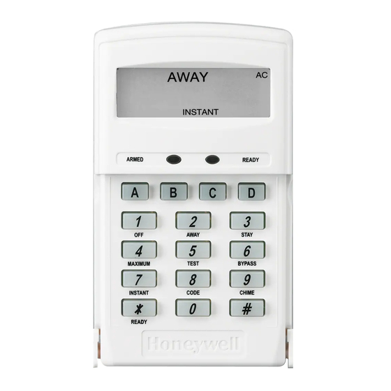
Figure 1 – 6149EX/6165EX Keypad
(shown with cover removed)
SPECIAL FUNCTION KEYS
The keypads also feature function keys. These keys may be
programmed for panic alarms or other special functions such
as macros. See the control's instructions for details.
Function keys must be held down for at least two (2) seconds
to activate an alarm. Key pairs activate immediately.
Special Function Keys
A or [1] and [✻]
B or [✻] and [#]
C or [3] and [#]
INSTALLATION AND SETUP GUIDE
2-digit
Custom
Zone
Zone
Identifier
Descriptors
Function
D
ADEMCO 6149EX & 6165EX
ADEMCO 6149EX & 6165EX
ADEMCO 6149EX & 6165EX
ADEMCO 6149EX & 6165EX
MOUNTING AND WIRING THE KEYPAD
The keypad must be mounted within the protected premises.
It can be surface mounted directly to walls. A built-in tamper
switch detects separation of the case-back from its mounting
surface. To include tamper protection, a tamper screw must be
inserted in the case-back, as shown in Figure 2.
NOTE: Not all control panels support keypad tamper reporting. Refer to
the individual Control Panel's Installation and Setup Guide.
Backlit
Display
*
1.
Separate the case back from the keypad.
2.
If using the tamper switch place the case back on a flat
surface and insert a screw through the tamper switch
plunger in the case back, as shown in Figure 2. Tighten
the tamper screw until the upper portion of the tab (near
the tamper screw) contacts the case back.
3.
Route wiring from the control panel through the opening
in the case back.
4.
Mount the case back to a wall.
5.
Wire directly from the keypad's terminal block to the
terminal block on the control board as follows:
Keypad
GL
−
+
MY
Refer to the control panel's Installation and Setup Guide for
more complete details.
6.
Reattach the keypad to its case back.
K6205EXV3 5/07 Rev. B
Remote Keypads
Remote Keypads
Remote Keypads
Remote Keypads
Figure 2 – Mounting the keypad
Wiring Table (All Keypads)
Control Panel
Data In
− Aux Pwr (GND)
+ Aux Pwr
Data Out
Wire Color
Green
Black
Red
Yellow
Advertisement

Related Manuals for Honeywell ADEMCO 6149ex


Summary of Contents for Honeywell ADEMCO 6149ex
- Page 1 INSTALLATION AND SETUP GUIDE GENERAL INFORMATION MOUNTING AND WIRING THE KEYPAD The ADEMCO 6149EX and ADEMCO 6165EX are The keypad must be mounted within the protected premises. addressable remote keypads designed for use with ADEMCO It can be surface mounted directly to walls. A built-in tamper control panels.
- Page 2 Honeywell Security and Custom Electronics Newhouse Industrial Estate, Motherwell 2 Corporate Center Drive Lanarkshire, ML1 5SB, Scotland, United Kingdom Melville, New York 11747 e-mail: hsuk64salesteam@honeywell.com www.honeywell.com/security Telephone: +44 (0)1698 738200 Copyright © 2007 Honeywell International Inc. ‡K6205EXV3uŠ K6205EXV3 5/07 Rev. B...