Table of Contents
Advertisement
Instructions for
Digitrip RMS 500 Trip Unit
Table of Contents
1 .0
General Description . . .... ...... . . .. ... ..... . .
1 .1
Protection .... . .. . ... ........... . .. ......... .
1.2
Information . ... .. .... . ... . ... . ... ... ..... .. . .
1 . 3
Testing . . ... .. . .. . ... . ... . ... . ... ... . . ... ... .
2. 0
UL Listed Devices . ... .... . . .. . ... ... .. . .. ... .
3 . 0
Principle of Operation . . ... . ... .... . . ..... ... .
3.1
General .... . ..... . ... . .. . .... . ... .. . .. .. ... .
3.2
Trip and Operation Indicators .. . ... ... .. .. ... .
3.3
Test Provisions . ....... . ... .... ... ..... ... .. .
3. 4
Making Current Release (Discriminator) .... .. .
3.5
Instantaneous Override . ........... . . ... .... .
3.6
Zone Interlocking ... .... . ... ....... ... .. . . . . .
4.0
Protection Settings .. . .... ... . ...... . .. . . ... . .
4.1
General ... ... ... ... . .. . . ...... . ... ... ..... . .
4.2
Long Delay Settings ..... . ... .... .......... . .
4.3
Long Delay Time Settings .... . ........ ... ... .
4.4
Short Delay Pick-up Settings ........ ... .. ... .
4.5
Short Delay Time Settings . ... ......... .. . .. .
4.6
Instantaneous Pick-up Settings . ... ... .. ... .. .
4.7
Ground Fault Current Pick-up Settings ....... .
4. 8
Ground Fault Time Delay Settings . ...... . . .. .
5.0
Integral Test Panel - Test Procedure ... .. ... . .
5.1
General .. ... .... ... . ... .... .......... .. ... . .
5.2
When To Test ....... ... .... ....... ... ..... . .
5.3
Test Provision ....... ... . .... ......... . . ... . .
5.4
Mode of Conducting Tests ... ......... ... .. . .
5. 4.1
Control Power ... .... .... . ....... . . . .. ... ... .
5. 4.2
By Not Tripping the Breaker ...... ... ..... ... .
5. 4.3
By Tripping the Breaker ....... ... ... ... ..... .
6 . 0
Back-up Battery .... ... ........ ... ... ... ... .. .
6 . 1
General . ... ... ... . ... ..... ... . ... .. . .... . .. .
6 . 2
Battery Check .. ... .... ........ ... ..... ..... .
6 . 3
Battery Replacement ........... ... . . . ....... .
7.0
Auxiliary Power Module . .... ... ...... ..... .. .
8.0
Rating Plug .. ... . ... .... .... ... ... ... ... . . .. .
9. 0
References . . ... . ... ........ ... ... . .. . . . .. .. .
9.1
Type DS Low Voltage AC Power Circuit
Breakers .. .... .... ........... ... ... ...... .
9.2
Type SPB Systems Pow-R Breakers ........ . . .
Digitrip RMS Trip Assemblies .... ... .. ..... . .
9.3
9.4
Series C® R-Frame Molded Case Circuit
Breakers ....... . ... ..... . .. ........... ... .
WARNING
DO NOT ATTEMPT TO INSTALL OR PERFORM MAIN
TENANCE ON EQUIPMENT WHILE IT IS ENERGIZED.
DEATH OR SEVERE PERSONAL INJURY CAN RESULT
FROM CONTACT WITH ENERGIZED EQUIPMENT.
ALWAYS VERIFY THAT NO VOLTAGE IS PRESENT
BEFORE PROCEEDING WITH THE TASK, AND
ALWAYS FOLLOW GENERALLY ACCEPTED SAFETY
PROCEDURES . THE WESTINGHOUSE ELECTRIC
CORPORATION IS NOT LIABLE FOR THE MISAPPLI
CATION OR MISINSTALLATION OF ITS PRODUCTS.
The user is cautioned to observe all recommendations, warn
ings and cautions relating to the safety of personnel and equip
ment, as well as all general and local health and safety laws,
codes, and procedures.
The recommendations and information contained herein are
based on Westinghouse experience and judgement, but should
Effective May, 1 98 9 Supersedes I. L. 2 9-8 5 1 dated March, 1 988
Page
not be considered to be all-inclusive or covering every appli
cation or circumstance which may arise. lf any questions arise,
contact Westinghouse Electric Corporation for further infor
1
mation or instructions.
1
1
1 . 0 General Description
1
1
1 . 1 Protection
4
4
4
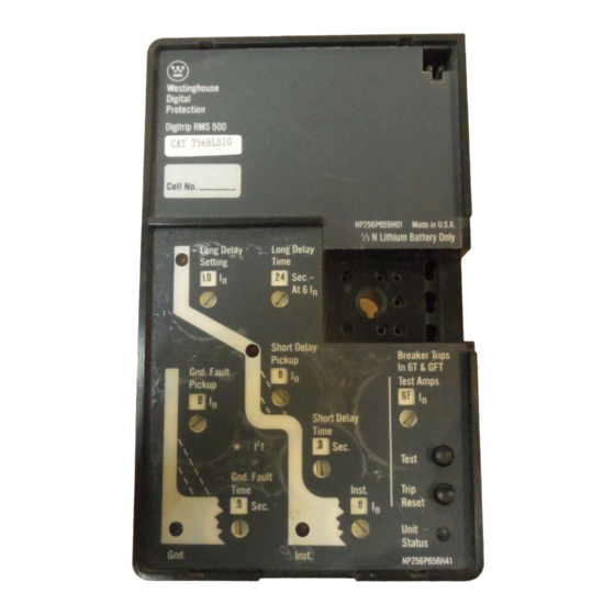
The Digitrip RMS 5 00 Trip Unit, illustrated in Fig. 1 , is a micro
5
processor based type trip suitable for use in type SPB Systems
5
Pow-R circuit breakers and types DS and DSL low voltage AC
5
power circuit breakers and Series C® R-Frame molded case
5
circuit breakers .
5
The trip unit provides true RMS current sensing for proper
5
6
correlation with thermal characteristics of conductors and
6
equipment. Interchangeable rating plugs are provided to estab
lish the continuous current rating of each circuit breaker.
6
6
6
The Digitrip RMS 5 00 Trip Unit is completely self-contained
6
and when the circuit breaker is closed, requires no external
6
control power to operate its
8
from current signal levels and control power derived through
8
current sensors integrally mounted in the circuit breaker.
8
8
The Digitrip RMS 5 00 Trip Unit is available in six optional pro
9
tection models. Each trip unit may be equipped with a maxi
9
mum of five phase and two ground (time-current) adjustments
9
to meet specific application requirements. These protection
9
models include the following types which are further illus
1 0
trated in the nameplate examples shown in Fig. 2.
1 0
1 0
Figure
1 0
1 0
2. 1
Long Time/Instantaneous
1 0
2.2
Long Time/Short Time
1 1
2.3
Long Time/Short Time/Instantaneous
2.4
Long Time/Instantaneous/Ground
1 1
2 . 5
Long Time/Short Time/Ground
1 1
2 . 6
Long Time/Short Time/Instantaneous/
1 1
Ground
1 1
1.2 Information
Red LED indicators are provided on the face of the trip unit
to indicate the mode of an automatic trip operation. A bat
tery is provided to maintain the mode of trip LED indication
following an automatic trip operation.
Green LEOs are provided to indicate the operational status of
the trip unit and the status of the back-up battery mounted in
the rating plug.
1 .3 Testing
An integral test panel, including a test selector switch and test
and reset pushbuttons, is provided to test the circuit breaker
in either a "Trip" or "No-Trip" test mode under qualified
conditions.
2.0 UL Listed Devices
Digitrip RMS 5 00 Trip Units are listed by the Underwriters
Laboratories, Inc. for use in types SPB, DS and DSL and
Series C R-Frame circuit breakers under UL File E7819.
I.L.
protection systems.
Type Protection
29-851 -A
It operates
Identifier
(LI)
(LS)
(LSI)
(LIG)
(LSG)
(LSI G)
Advertisement
Table of Contents

Summary of Contents for Westinghouse Digitrip RMS 500
- Page 1 The recommendations and information contained herein are Laboratories, Inc. for use in types SPB, DS and DSL and based on Westinghouse experience and judgement, but should Series C R-Frame circuit breakers under UL File E7819. Effective May, 1 98 9 Supersedes I. L. 2 9-8 5 1 dated March, 1 988...
- Page 2 Curve Integral Test Module Curve Typical Setting Trip Unit Reset Pushbutton Viewing Window Typical Setting Adjustment Typical Digitrip RMS 500 Trip Unit with Rating Plug Installed Fig. 1 Westinghouse Westinghouse Digital Digital ProtectiOn Protection Digitrip RMS Digitrip RMS Cell No .
- Page 3 Westinghouse Westinghouse D1gital Digital Protection Protection D1gitr1p RMS D1g1tr1p RMS Cell No. Made Made U.S.A U S.A NP256P655HOI NP256P655HOI '/, N Lithium Battery Only Long Delay Long Delay Long Delay Long Delay Time Settmg Time OJ I n [DSec- [DSec [!]In ·...
- Page 4 �- ---------- --- ------ - - --- - -------- ------ ---- Auxiliary Power Module Input (When Used) Trip r--------' CT's Bridge Circuits Summing ower Supply Rating Plug ;ypical Phase or G round Calibration Resistor 3 Digitrip RMS 500 Block Diagram with Breaker Interface Fig.
- Page 5 3.3 Test Provisions 3.5 Instantaneous Override An i ntegral test panel, including a test selector switch and test In addition, when the Digitrip RMS 5 00 Trip Unit is not equipped and reset pushbuttons, is provided to test the circuit breaker with an adjustable instantaneous setting, i .e., types LS or LSG, i n either a TRIP o r NO-TRIP test mode under qualified condi...
- Page 6 Time-Cu rrent curves a re pictured on the face of the Digitrip RMS 500 Tri p Unit since it is completely self-powered trip u nit. The particular setting to be adjusted is located in close using only the i nput from the i nsta l led cu rrent sensors.
- Page 7 ("1. Available Settings Short Delay 0.5, 0.6, 0.7' 0.8, I � Time 0.85, 0.9, 0.95, 1.0 .._ __ __ � Sec. In Multiples of '.r"" Rating Plug Amperes (I n ) ""'- " � Available Settings Fig. 4.1 Long Delay Ampere Pickup Settings 0.1' 0.2, 0.3, 0.4, 0.5 :'">..
- Page 8 *automatically aborted by the trip un it. Response Si nce the Digitrip RMS 500 Trip Unit is completely self-pow Returns to Flat ered using energy derived from the cu rrent sensors i nsta l led Response at...
- Page 9 test. The value of the simulated test current is 1 .0 per unit of Should an actual overload or fault condition occur during an the rating plug value. i n-service, "No Trip Test" sequence, the protection function wi l l override the test function, and the circuit breaker wi l l trip automatical ly as pre-prog rammed with the various Time-Cur...
- Page 10 When d rawout construction is provided, any circuit breaker tion of the battery check LED as shown in Fig. 6. 1 . If the battery equipped with a Digitrip RMS 500 Trip U n it can be conveniently check LED does not tu rn "ON", replace the battery.
- Page 11 9.0 References 9.3 Digitrip RMS Trip Assemblies 9. 1 Type OS Low Voltage AC Power Circuit Breakers I .L. 29-851 Instructions for Digitrip R M S 500 Trip U nit I . B . 33-790-I F Instructions for Low-Voltage Power Circuit I.L.
- Page 12 Westinghouse Electric Corporation Distribution and Control Busi ness U nit Electrical Components Division Pittsbu rgh, PA 1 5220 Style No. 661 5C96H01...
-
Page 13: General Description
Digitrip RMS 500 Trip U n its are l i sted by the Underwriters The recommendations and information contained herein a re Laboratories, Inc. for use in types SPB, DS and DSL and based on Westinghouse experience and judg ement, but should Series C R-Frame ci rcuit breakers under U L File E781 9. - Page 14 Must Use With Sensor Ratet! Plug iRalet!ll 6i Hz Only Curve ··��-- Curve Typical Setting Viewing Window Adjustment Typical Digitrip RMS 500 Trip Unit with Rating Plug Installed Fig. 1 Westinghouse Westinghouse Digital D1gttal Protectmn Protection Digitrip RMS Dig1tr1p RMS Cell No...
- Page 15 ® ® Westinghouse Westinghouse Dig1tal D1g1tal Protection Protection Digitrip RMS Digitnp RMS Cell No. Cell No. Made Made ' / o N U.S A U.S A. NP256P655H01 NP256P655H01 lithium Battery Only lithium Battery Only long Delay long Delay long Delay...
-
Page 16: Principle Of Operation
Fig . 3. in the related segment of the time-current curve depicted on In the Digitrip RMS 500 Trip Unit all requ i red sensing and the face of the trip u nit. The mode of trip is identified by the... -
Page 17: Test Provisions
3.5 Instantaneous Override An i ntegral test panel, i ncluding a test selector switch and test In addition, when the Digitrip RMS 500 Trip Unit is not equipped and reset pushbuttons, is provided to test the circuit breaker with a n adjustable i n stantaneous setting, i.e., types LS o r LSG, i n either a TRIP or NO-TRI P test mode u nder qualified condi... - Page 18 factor of the protection model su pplied as i l lustrated in Figs. cific i nformation is also shown on the rati ng plug and on the 2.1 through 2.6. Each setti ngs is made with a n eight position appl icable Time-Current cu rve.
- Page 19 "" Available S�tt�gs I I J l l l � Short Delay 0.5, 0.6, 0.7' 0.8, . � Time 0.85, 0.9 , 0.95, 1 .0 ---- -- -. .. I � � Sec. In Multiples of '/" Rating Plug Amperes U n l 1 "- Available Settings "...
- Page 20 *automatically aborted Response Since the Digitrip RMS 500 Trip Unit is com pletely self-pow Returns to Flat ered using energy derived from the current sensors instal led Response at...
- Page 21 test. The value of the simulated test cu rrent is 1 .0 per unit of Should an actual overload or fault condition occur d u ring an in-service, "No Trip Test" sequence, the protection function the rating plug value. wi l l override the test function, and the circuit breaker wi l l trip automatical ly as pre-prog rammed with the various Time-Cur...
-
Page 22: Back-Up Battery 1
Trip Unit Plug Receptacle Fig. A uxiliary Power Module 6. Reset and reclose the ci rcuit breaker fol lowing establ ished CAUTION operating procedures. CARE SHOULD BE EXERCISED WHEN R EPLACING A 6.0 Back-up Battery BATTERY TO I NSURE THAT THE CORRECT POLAR ITIES ARE OBSERVED. - Page 23 9.0 References 9.3 Digitrip RMS Trip Assemblies 9 . 1 Type DS Low Voltage AC Power Circuit Breakers I . L. 29-851 Instructions for Digitrip RMS 500 Trip U nit I.B. 33-790-IF Instructions for Low-Voltage Power Circuit I . L. 29-852...
- Page 24 Westinghouse Electric Corporation Distribution and Control B usiness Unit Electrical Components Division Pittsbu rgh, PA 1 5220 Styl e No. 661 5C96H01...
-
Page 25: Table Of Contents
When To Test ....... The Digitrip RMS 500 Trip U nit is available in six optional pro... - Page 26 Hz Only Curve ··�--, ' Integral Test Module Curve Typical Setting Viewing Window Typical Setting Adjustment Typical Digitrip RMS 500 Trip Unit with Rating Plug Installed Fig. 1 ® ® Westinghouse Westinghouse Digital D1g1tal Protect1on Protect1on Digitnp RMS Digitrip RMS Cell No .
-
Page 27: Long Delay Settings
® ® Westinghouse Westinghouse 01g1tal D1gital Protection Protection D1gitnp RMS Digitnp RMS Cell No. Cell No U S. A U.S.A. Made Made 1/ 3 NP256P655HOI NP256P655H01 N Lith1um Battery Only N L1th1um Battery Only Long Delay Long Delay Long Delay... -
Page 28: Long Delay Time Settings
factor of the protection model suppl ied as i l lustrated in Figs. cific i nformation is a l so shown on the rating plug and on the 2.1 through 2.6. Each settings is made with a n eight position appl icable Time-Current cu rve. - Page 29 ('-1. Available Settings Long Delay Setting Short Delay � � 0.5, 0.6, 0.7' 0.8, Time 0.85, 0.9, 0.95, 1 .0 � I � Sec. In Multiples of '/'" Rating Plug Amperes !l n l I � Available Settings " � u Fig.
-
Page 30: Integral Test Panel - Test Procedure
1 2 t Response Si nce the Digitrip RMS 500 Trip U n it is completely self-pow Returns to Flat ered using energy derived from the cu rrent sensors i n sta lled... -
Page 31: Mode Of Conducting Tests
test. The value of the s i m u l ated test current is 1 .0 per u n it of Should an actual overload or fau lt condition occur d u ring an the rating plug value. i n-service, "No Trip Test" sequence, the protection function wi l l override the test fu nction, and the circu it breaker will trip automatically as pre-program med with the various Time-Cur... -
Page 32: Back-Up Battery
When d rawout construction is provided, any circuit breaker tion of the battery check LED as shown in Fig. 6. 1 . If the battery equipped with a Digitrip RMS 500 Trip U n it can be conveniently check LED does not tu rn "ON", replace the battery. -
Page 33: References
9.0 References 9.3 Digitrip RMS Trip Assemblies 9. 1 Type OS Low Voltage AC Power Circuit Breakers I . L. 29-851 I nstructions for Digitrip RMS 500 Trip Unit I.B. 33-790-IF Instructions for Low-Voltage Power Circuit I . L. 29-852... - Page 34 Westinghouse Electric Corporation Distribution and Control Busi ness Unit Electrical Components Division Pittsburgh, PA 1 5220 Style No. 661 5C96H01...