Advertisement
Quick Links
S
UPERMICR
R
• www.supermicro.com (Email: support@supermicro.com)
• Manuals: http://www.supermicro.com/support/manuals
X9DRL-3F/X9DRL-iF
• Drivers & Utilities: ftp://ftp.supermicro.com
Q
R
G
R
. 1.00
UICK
EFERENCE
UIDE
EV
• Safety: http://www.supermicro.com/about/policies/safety_information.cfm
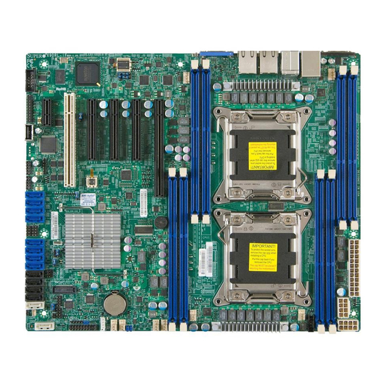
Motherboard Layout and Features
1
1 0
BMC Firmware
1
1 5
1 2
1
FAN6
BMC CTRL
JPL2
1 4
1
JPL1
1
1 6
1
1 3
LAN CTRL
LAN CTRL
1 1
1
1
1 7
1
1 8
1
1 9
CPLD
1
2 0
BIOS
1
2 1
X9DRL-iF
S-SAS7
Rev. 1.01
S-SAS6
1
2 2
S-SAS5
S-SAS4
2 4
1
S-SGPIO1
S-SGPIO2
BUZZER
1
2 3
Intel PCH
SAS/SATA3
SAS/SATA2
1
2 5
SAS/SATA1
SAS/SATA0
I-SATA5
2 6
1
I-SATA4
1
2 7
I-SATA3
I-SATA2
Battery
T-SGPIO2
1
3 4
3 1
1
I-SATA1
1
2 8
3 7
1
1
1
2 9
4 2
JSTBY1
1
4 3
1
3 2
T-SGPIO1
FANB
FAN3
1
3 6
FANA
FAN4
3 3
1
JD1
1
3 0
2 8
1
JF1
I-SATA0
1
3 8
3 9
1
1
4 0
1
4 1
1
1
1
3 5
4 4
4 5
= mounting hole
CPU Installation
Heatsink Installation
Screw #4
CPU Keys
Screw #1
Socket Keys
1.
2.
Motherboard
Mounting Hole
Note: Graphics shown in this quick reference guide are for illustration only. Your components may or may not look exactly the same as drawings shown in this
C
I
ONTACT
NFORMATION
1
9
KB/MOUSE
1
8
USB6/7
1
1
LED1
VGA
1
3
COM1
UID
JUIDB1
1
7
1
6
FAN5
1
5
1
4
LAN2
LAN1
USB8/9
IPMI_LAN
1
2
CLOSE 1st
CPU2
OPEN 1st
CLOSE 1st
JPW4
CPU1
OPEN 1st
JPW2
1
5 0
FAN2
1
4 7
1
4 6
1
4 8
4 9
1
Note: Item numbers are listed in counterclockwise order.
Front Panel Control (JF1)
20
19
Ground
NMI
Screw #2
X
X
FP PWRLED
3.3 V Stby
HDD LED
3.3V Stby
Screw #3
NIC1 Link LED
3.3V Stby
3.3V Stby
NIC2 Link LED
Blue+ (OH/Fan Fail/
Red+ (Blue LED Cathode)
PWR FaiL/UID LED)
Power Fail LED
3.3V Stby
Reset
Reset Button
Ground
Power Button
Ground
PWR
2
1
guide.
P
C
ACKAGE
ONTENTS
(Applies to single-pack only)
• One (1) Supermicro Motherboard
• Six (6) Serial ATA Cables (X9DRL-iF)
• Eight (8) Serial ATA Cables (X9DRL-3F)
• One (1) I/O Shield
Jumpers, Connectors and LED Indicators
Jumpers
Jumper
Item #
Description
JBT1
26
Clear CMOS
JI
2
C1/JI
2
C2
43, 42
SMB to PCI-E Slots
JPB1
14
BMC Enabled
JPG1
18
VGA Enabled
JPL1/JPL2
13, 12
GLAN1/GLAN2 Enable
JWD1
31
Watch Dog Timer Enable
Connectors
Connector
Item #
Description
COM1/COM2
1, 16
Back Panel COM Port1 / Front Accessible COM2 Header
Fan 1~3
47, 46, 45
CPU/System Fan Headers
Fan 4-6
44, 2, 11
CPU/System Fan Headers
FanA, FanB
41, 40
CPU/System Fan Headers
JD1
36
Speaker/Power LED Indicator
JF1
35
Front Panel Control Header
JIPMB1
38
4-pin External BMC I
2
C Header (for an IPMI Card)
JL1
29
Chassis Intrusion
JOH1
32
Overheat LED Indicator
JPI
2
C1
48
Power Supply SMBbus I
2
JPW1/2
49, 50
12V 8-Pin Power Connectors
1
5 1
JPW4
51
24-Pin ATX Main Power Connector
JSD1
30
SATA DOM (Device on Module) Power Connector
JSTBY1
37
+5V Standby Power Header
JTPM1
17
TPM (Trusted Platform Module)/Port 80
JUIDB1
9
UID (Unit Identifi cation) Switch
LAN1/LAN2
6, 7
G-bit Ethernet Ports 1/2
(IPMI) LAN
4
IPMI Dedicated LAN
(I-)SATA0~1
28
Intel PCH SATA Connectors 0/1
(I-)SATA2~5
27
Intel PCH SATA Connectors 2~5
(S-)SATA0~3
25
SATA Connectors 0~3 (X9DRL-iF)
(S-)SAS0~7
22
SAS Connections 0~7 (for X9DRL-3F only)
(S-)SGPIO1/2
24, 23
Serial (SAS) General Purpose I/O Headers 1/2
(T-)SGPIO1/2
33, 34
Serial (SATA) General Purpose I/O Headers 1/2
USB 0/1, 2/3
21, 20
Front Panel USB Connections 0/1, 2/3
USB 4
19
FP-Accessible Type A USB Connections 4
USB 6/7, 8/9
3, 5
Backpanel USB Connections 6/7, 8/9
VGA
8
Backpanel VGA Port
LED Indicators
LED
Item #
Description
Color/State
LED1
10
Rear UID LED
Blue: On
LED2
39
Onboard PWR LED
Green: On
LEDM1
15
BMC Heartbeat LED
Green
Note: Refer to Chapter 2 of the User Manual for detailed information on jumpers, connectors, and LED indicators.
Memory Support
This motherboard supports up to 256 GB of Registered (RDIMM)/Load Reduced
Default
(LRDIMM) ECC or up to 64 GB of Unbuffered (UDIMM) ECC/Non-ECC DDR3
See Chpt. 2 in User Manual
800/1066/1333/1600 MHz 4-channel memory in 8 DIMM slots.
Off (Disabled)
Note: For memory optimization, use only DIMM modules that have been validated by Supermicro.
Pins 1-2 (Enabled)
For the latest memory updates, please refer to our website at http://www.supermicro.com/
Pins 1-2 (Enabled)
products/motherboard.
Pins 1-2 (Enabled)
Pins 1-2 (Reset)
Insert the desired number of DIMMs into the memory slots, starting with P1-DIMMA1.
For memory to work properly, follow the tables below for memory population order.
Refer to the motherboard layout (at left) for the location of the DIMM slots.
Processors and their Corresponding
CPU#
CPU1
CPU2
Processor and Memory Module Population
C Header
Number of
CPUs+DIMMs
1 CPU &
CPU1
2 DIMMs
P1-DIMMA1/P1-DIMMB1
1 CPU &
CPU1
4 DIMMs
P1-DIMMA1/P1-DIMMB1, P1-DIMMC1/P1-DIMMD1
2 CPUs &
CPU1 + CPU2
2 DIMMs
P1-DIMMA1, P2-DIMME1
2 CPUs &
CPU1 + CPU2
4 DIMMs
P1-DIMMA1/P1-DIMMB1, P2-DIMME1/P2-DIMMF1
2 CPUs &
CPU1 + CPU2
6 DIMMs
P1-DIMMA1/P1-DIMMB1/P1-DIMMC1, P2-DIMME1/P2-DIMMF1/P2-DIMMG1
2 CPUs &
CPU1 + CPU2
8 DIMMs
P1-DIMMA1/P1-DIMMB1/P1-DIMMC1/P1-DIMMD1, P2-DIMME1/P2-DIMMF1/P2-
DIMMG1/P2-DIMMH1
D
F
Status
Unit Identifi ed
A
C
Power On
B
BMC Normal
Note: Refer to Chapter 2 of the User Manual for detailed information on memory support and CPU/
motherboard installation instructions.
DIMM Installation
Memory Modules
Corresponding DIMM Modules
P1-
P1-
P1-
P1-
DIMMA1
DIMMB1
DIMMC1
DIMMD1
P2-
P2-
P2-
P2-
DIMME1
DIMMF1
DIMMG1
DIMMH1
CPU and Memory Population Confi guration Table
(*For memory to work properly, please install DIMMs in pairs)
Back Panel IO Connectors
A. COM 1
F. USB 3
B. USB 0
G. GLAN1
C. USB 1
H. GLAN2
D. IPMI LAN
I. VGA
E
G
H
E. USB 2
J. UID
I
J
Advertisement


