Table of Contents
Advertisement
Advertisement
Chapters
Table of Contents

Related Manuals for NAD L75


Summary of Contents for NAD L75
- Page 1 © NAD 2001 NAD ELECTRONICS INTERNATIONAL TORONTO...
- Page 2 A/V RECEIVER...
-
Page 3: Table Of Contents
SECTION 1 SUMMARY CONTENTS PRODUCT SAFETY SERVICING GUIDELINES..................1-4 SERVICING PRECAUTIONS ........................1-5 * General Servicing Precautions * Insulation checking prodedure * Electrostatically Sensitive Devices SPECIFICATIONS ............................1-6 LOCATION OF CUSTOMER CONTROLS ..................1-7 ~ 1-8 EXPLODED VIEW ..........................1-9 ~ 1-10... -
Page 4: Product Safety Servicing Guidelines
PRODUCT SAFETY SERVICING GUIDELINES CAUTION : DO NOT ATTEMPT TO MODIFY THIS PRODUCT IN VOLTAGE MEASURE MUST NOT EXCEED 75 VOLTS R.M.S. ANY WAY. NEVER PERFORM CUSTOMIZED INSTALLATIONS THIS CORRESPONDS TO 0.5 MILLIAMP AC ANY VALUE WITHOUT MANUFACTURER’S APPROVAL. UNAUTHORIZED EXCEEDING THIS LIMIT CONSTITUTES A POTENTIAL MODIFICATIONS WILL NOT ONLY VOID THE WARRANTY, BUT SHOCK HAZARD AND MUST BE CORRECTED IMMEDIATELY. -
Page 5: Servicing Precautions
SERVICING PRECAUTIONS CAUTION : Before servicing the A/V Receiver covered by this Electrostatically Sensitive (ES) Devices service data and its supplements and addends, read and follow the Some semiconductor (solid state) devices can be damaged easily by SAFETY PRECAUTIONS. NOTE : if unforeseen circumstances static electricity. -
Page 6: Specifications
SPECIFICATIONS Amplifier Section FM Tuner Section (Without notes 100.1 MHz, 65 dBf) Output Power (Front) : F.T.C Rating: Tuning Range : 60 watts RMS per channel minimum, both channels 87.5 MHz - 108.0 MHz C: 50 kHz steps driven into 8 ohms from 20 Hz to 20kHz with no AH: 100 kHz steps more than 0.09% total harmonic distortion AM Suppression Ratio: C: 45 dB... -
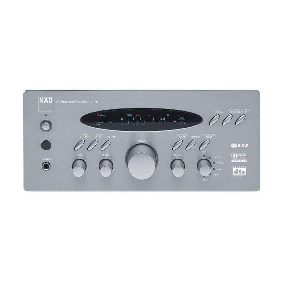
Page 7: Location Of Customer Controls
LOCATION OF CUSTOMER CONTROLS FRONT PANEL VFL Display POWER STANDBY/ON button BASS/TREBLE BALANCE Tone Controls Control PHONES MASTER VOLUME SOURCE SELECTOR Control Control REAR PANEL S-VIDEO Signal jacks AUDIO Signal jacks Dolby Digital / DTS / PCM DIGITAL IN jacks (For AH version only) PRE OUT jack SPEAKER terminals... -
Page 8: Remote Control
5. TEST TONE button (L75) 6. NUMERIC button (L75/L55) 7. PROGRAM button (L55) 8. OSD ON/OFF button (L75), DVD SET UP button (L55) 9. DIGITAL INPUT/RDS button (L75), DVD DISPLAY button (L55) 10. TITLE button (L55) 11. MENU buttons (L55) 12. -
Page 9: Exploded View
EXPLODED VIEW DESCRIPION PARTS-NO Q,ty SCREW KTS3+8J AL PANEL KKM1A105ZC26 SPECIAL SCREW KHD1A016 SIDE BAR KKM1A062C26 SCREW KTB3+6J RUBBER , TRANS KHG1A198 SCREW KTB3+6F 22 AH VOLUME KNOB ASS'Y KGK1A063ZA SCREW KTB3+10G VOLUME KNOB ASS'Y(B) KGK1A064ZA SCREW KTWS3+10G 27 X10 VOLUME KNOB ASS'Y(A) KGK2A064YA SCREW... - Page 10 SECTION 2 ELECTRICAL CONTENTS CONTENTS IC BLOCK DIAGRAMS & PIN DESCRIPTION ..................2-11 1. IC81 (TMP87PS71F u-COM) ......................2-12 2. IC34 (YSS912C AC3/DTS Decoder) ....................2-14 3. IC84 (NJU3713G EXPANDOR) ......................2-16 4. IC32 (AK4112VF DIR) ......................... 2-17 5. IC33 (AK4527VQ CODEC) ........................2-17 6.
- Page 11 IC PIN FUNCTION (IC81 : TMP87PS71F-ANAM 1328AT OTP, UCOM) PIN No. SYMBOL DESCRIPTION Not Use (No connection) REMOTE IN Remote Control Sensor Data Input RDS CLK RDS IC (SA6579TV1) CLK/Data Port RDS DATA Function Mute Function Mute Control Output port (Active “H”) EVOL Data EVOL CLK Electronic Vol.
- Page 12 u-COM IC PIN ASSIGNMENT & BLOCK DIAGRAM PIN ASSIGNMENTS (TOP VIEW) 54 53 52 51 50 49 48 47 46 45 44 43 42 41 (SIS) P97 P66 (G9) P65 (G10) (KEY0) P40 P64 (G11) (KEY1) P41 P63 (G12) (KEY2) P42 P62 (G13) (KEY3) P43 P61 (G14)
- Page 13 AC 3/DTS DECODER (YSS912C:IC34) PIN No. SYMBOL DESCRIPTION 1,31,71 VDD1 +5V Power Supply(for I/Os) RAMCEN External SRAM interface /CE RAMA16 External SRAM interface address 16 (not use) RAMA15 External SRAM interface address 15 (not use) SDIB0 PCM input 0 to Sub DSP(not use) SDIB1 PCM input 1 to Sub DSP(not use) SDIB2...
- Page 14 PIN No. SYMBOL DESCRIPTION RAMA2 External SRAM interface address 2 72 ~ 79 RAMD0~7 I+/O External SRAM interface data (STREAM0~7 output when External SRAM is not in use) SDWCK0 Word clock input for SDIA, SDOA, SDIB, SDOB SDBCK0 Bit clock input for SDIA,SDOA,SDIB,SDOB SDIA0 AC-3 Bitstream (or PCM) data input for Main DSP SDIA1...
- Page 15 YSS912C BLOCK DIAGRAM Microprocessor Coefficient Interface Program RAM Control Signals Control Signals Control Registers SDBCK1 SDWCK1 /SDBCK0 SDBCK0 SDWCK0 SDOACKSEL SDOBCKSEL SDOBCKSEL SDOB0 LS,RS SDIA0 SDOB1 C, LFE SDOB2 SDIA1 SDOB3 STREAM 0~7 SURENC External RAM KARAOKE Operating clock interface Data RAM MUTE (30MHz)
- Page 16 AK4112AVF (DIR IC32) AVSS AVDD MCKO1 MCKO2 Clock Clock X’tal Recovery Generator Oscillator Input Selector 96kHz FS96 Detect DAUX LRCK BICK Audio V/TX DAIF SDTO Decoder DVDD DVSS TVDD System CCLK CDTO Control AC-3/MPEG Error Detect CDTI Detect AUTO P/S="L" [Serial Control Mode] AV4527VQ (CODEC IC33) RX2 RX3 RX4...
- Page 17 NJM2296M (VIDEO SW / IC21, 22, 23) BLOCK DIAGAM (NJM2296M /MAIN IC96) Vin1 Vin2 Vout1 6.2dB dirver Vin3 6.2dB Vout2 dirver Vin4 6.2dB Vout3 dirver Vin5 OPA2134UA / NJM 2068MD) (OP AMP / IC12~15, 37~42, 82) IS61C256A15J (256K SRAM. IC35) 256 x 1024 A0-A14 MEMORY ARRAY...
- Page 18 TC9164AF (FUNCTION IC36) BLOCK DIAGRAM R-COM L-COM L-COM R-COM L-COM R-COM DATA SHIFT REGISTER TC9163AF (FUNCTION IC11) BLOCK DIAGRAM R-COM L-COM L-COM R-COM L-COM R-COM DATA SHIFT REGISTER 2-19...
- Page 19 TC9482F (ELECTRONIC VOLUME IC16) TEST (SUB) L-OUTA R-OUTA (SUB) L-INA R-INA latch L-A-GNDA R-A-GNDA latch (LS) L-OUTB R-OUTB 3 to 7 (LS) L-INB R-INB decoder Same as L-ch latch Circuit L-A-GNDB 4 to 13 R-A-GNDB latch decoder (RS) L-OUTC R-OUTC (RS) L-INC 10 R-INC...
- Page 20 ANAM 2024V (OSA IC25) Decoder 2-21...
-
Page 21: Transistor, Regulator Ic Block Diagram
SAA6579TV1 (RDS FILTER IC83) 47 pF 82 pF 4.332/8.664 MHz 2.2 kΩ V DDD OSCI OSCO OSCILLATOR QUAL 57 kHz signal ANTI- QUALITY BIT RECONSTRUCTION BANDPASS ALIASING GENERATOR FILTER (8th ORDER) FILTER DIVIDER 330 pF SCOUT 560 pF BIPHASE COSTAS LOOP RDDA CLOCKED DIFFERENTIAN... -
Page 22: Diagrams
1. BLOCK DIAGRAM 2-23 2-24... - Page 23 BLOCK DIAGRAM 2-25 2-26...
-
Page 24: Wiring Diagram
2. WIRING DIAGRAM 2-27 2-28... -
Page 25: Schematic Diagram
3. SCHEMATIC DIAGRAMS MAIN SCHEMATIC DIAGRAMS 2-29 2-30... - Page 26 u-COM & GUIDE CIRCUIT DIAGRAM 2-31 2-32...
- Page 27 INPUT SCHEMATIC DIAGRAM 2-33 2-34...
- Page 28 AMP, SPEAKER, SUB TRANS & AC OUTLET CIRCUIT DIAGRAM 2-35 2-36...
- Page 29 SURROUND CIRCUIT DIAGRAM 2-37 2-38...
- Page 30 SURROUND CIRCUIT DIAGRAM 2-39 2-40...
- Page 31 4. PRINTED CIRCUIT DIAGRAMS MAIN PCB 2-41 2-42...
-
Page 32: Front
FRONT PCB 2-43 2-44... - Page 33 AMP / SPEAKER PCB 2-45 2-46...
- Page 34 SURROUND PCB 2-47 2-48...
-
Page 35: Electrical Parts List
SECTION 3 ELECTRICAL PARTS LIST RESISTORS AND CAPACITORS Notes : • Part numbers are indicated for most mechanical parts. Please use this part number for parts order. • The unit of resistance is OHM (Ω) K=1000 (Ω), M=1000 (KΩ) • The unit of capacitance is MICROFARAD (µF) P=10 µF Numbering System of Resistor... - Page 36 LOAD NO. PART NO. DESCRIPTION SPECIFICATION C957 , C958 KCQI1H102JZT CAP , MYLAR 1000PF 50V J C959 KCEA1HH1R0T CAP , ELECT 1.0UF 50V D791 KVD1N4148MT DIODE 1N4148 D910 , D911 KVDMTZJ6.2BT DIODE , ZENER 6.2V 1/2W L271 KLQ220J405T COIL , PEAKING(RADIAL) 22UH J 4X5 L272 KLQ5R6J405T...
- Page 37 LOAD NO. PART NO. DESCRIPTION SPECIFICATION CN51 , CN52 BJP06GA130ZK CONNECTOR (SOCKET) TAC-L06X-A3 CN61 , CN62 BJP06GA130ZK CONNECTOR (SOCKET) TAC-L06X-A3 CN71 , CN72 BJP06GA130ZK CONNECTOR (SOCKET) TAC-L06X-A3 CN75 BJP13GA98ZM CONNECTOR (SOCKET) TAC-L13X-A3 CN76 KJP03GA98ZM WAFER MOLEX35336-0310 CN78 KJP04GA01ZM WAFER MOLEX5276-04A C901 , C902 KCET63VAH123N CAP , ELECT...
- Page 38 LOAD NO. PART NO. DESCRIPTION SPECIFICATION C813 , C814 KCFE1J123JBT CAP , FILM 0.012UF 63V J C815 , C816 KCFE1J683JBT CAP , FILM O.068UF 63V J C817 , C818 KCBS1H223ZFT CAP , CERAMIC 0.022UF 50V Z C825 KCBS1H223ZFT CAP , CERAMIC 0.022UF 50V Z C826 KCEA1CKS101T...
-
Page 39: Input
LOAD NO. PART NO. DESCRIPTION SPECIFICATION R821 KRD20TJ102T RES , CARBON 1K OHM 1/4W J R822 KRD20TJ102T RES , CARBON 1K OHM 1/5W J R830 KRD20TJ272T RES , CARBON 2.7K OHM 1/5W J R831 , R832 JRD20TJ223T RES , CARBON 22K OHM 1/5W J R833 , R834 JRD20TJ101T... - Page 40 LOAD NO. PART NO. DESCRIPTION SPECIFICATION R111 ~ R124 KRD20TJ104T RES , CARBON 100K OHM 1/5W J R125 ~ R128 KRD20TJ471T RES , CARBON 470 OHM1/5W J R129 ~ R131 KRD20TJ102T RES , CARBON 1K OHM 1/5W J BN84 KJP12GB99ZM CONNECTOR MOLEX 35237-1210 JK11 , JK12...
- Page 41 LOAD NO. PART NO. DESCRIPTION SPECIFICATION PCB7 KUP11396-7 PCB , GUIDE C859 ~ C864 KCBS1H220JC CAP , CERAMIC 22PF 50V J C881 KCBS1H223ZFT CAP , CERAMIC 0.022UF 50V Z C882 KCEA1AKS101T CAP , ELECT 100UF 10V C883 KCKT1H182KB CAP , CERAMIC 1800PF 50V K C884 KCEA1VH100T...
-
Page 42: Surround
LOAD NO. PART NO. DESCRIPTION SPECIFICATION R503 ~ R506 KRD20TJ473T RES , CARBON 47K OHM 1/5W J R507 , R508 KRD20TJ271T RES , CARBON 270 OHM 1/5W J R509 , R510 KRD20TJ560T RES , CARBON 56 OHM 1/5W J R511 ~ R514 KRD20TJ150T RES , CARBON 15 OHM 1/5W J... - Page 43 LOAD NO. PART NO. DESCRIPTION SPECIFICATION C607 , C608 KCCT1H150JC CAP , CERAMIC 15PF 50V J C609 , C610 KCKT1H181KB CAP , CERAMIC 180PF 50V K C611 , C612 KCQI1H223JZT CAP , MYLAR 0.022UF 50V J C617 , C618 KCQI1H223JZT CAP , MYLAR 0.022UF 50V J C619 , C620...
- Page 44 LOAD NO. PART NO. DESCRIPTION SPECIFICATION R712 ~ R714 KRD20TJ561T RES , CARBON 560 OHM 1/5W J R715 , R716 KRD20TJ472T RES , CARBON 4.7K OHM 1/5W J R717 , R718 KRD20TJ561T RES , CARBON 560 OHM 1/5W J R719 , R820 KRD20TJ223T RES , CARBON 22K OHM 1/5W J...
- Page 45 LOAD NO. PART NO. DESCRIPTION SPECIFICATION C523 ~ C526 KCQI1H102JZT CAP , MYLAR 1000PF 50V J C621 , C622 KCQI1H473JZT CAP , MYLAR 0.047UF 50V J C623 ~ C626 KCQI1H102JZT CAP , MYLAR 1000PF 50V J C757 KCQI1H473JZT CAP , MYLAR 0.047UF 50V J C759 , C761 KCQI1H102JZT...
-
Page 46: Surround
LOAD NO. PART NO. DESCRIPTION SPECIFICATION CN63 KJP04GB03ZM WAFER MOLEX 5267-04A CN73 KJP07GA98ZM WAFER MOLEX 35336-0710 CN74 KJP04GA98ZM WAFER MOLEX 35336-1010 SURR B'D (KUP11398-1,2) PCB1 KUP11398-1 PCB , SURROUND-1 C363 , C364 KCQI1H222JZT CAP , MYLAR 2200PF 50V J C365 , C366 KCFT1H104ZF CAP , SEMI 0.1UF 50V Z... - Page 47 LOAD NO. PART NO. DESCRIPTION SPECIFICATION R369 ~ R372 KRD20TJ471T RES , CARBON 470 OHM 1/5W J R373 ~ R376 KRD20TJ472T RES , CARBON 4.7K OHM 1/5W J R377 ~ R382 KRD20TJ4R7T RES , CARBON 4.7 OHM 1/5W J R383 , R384 KRD20TJ104T RES , CARBON 100K OHM 1/5W J...
- Page 48 LOAD NO. PART NO. DESCRIPTION SPECIFICATION C351 ~ C353 KCBS1H181KBT CAP , CERAMIC 180PF 50V K C355 , C356 KCEA1CKS100T CAP , ELECT 10UF 16V C357 , C358 KCKT1H223ZF CAP , CERAMIC 0.022UF 50V Z C359 KCKT1H471KB CAP , CERAMIC 470PF 50V K C360 KCEA1CKS100T...
- Page 49 LOAD NO. PART NO. DESCRIPTION SPECIFICATION R349 , R350 KRD20TJ122T RES , CARBON 1.2K OHM 1/5W J R351 , R352 KRD20TJ183T RES , CARBON 18K OHM 1/5W J R353 , R354 KRD20TJ113T RES , CARBON 11K OHM 1/5W J R355 , R356 KRD20TJ101T RES , CARBON 100 OHM 1/5W J...