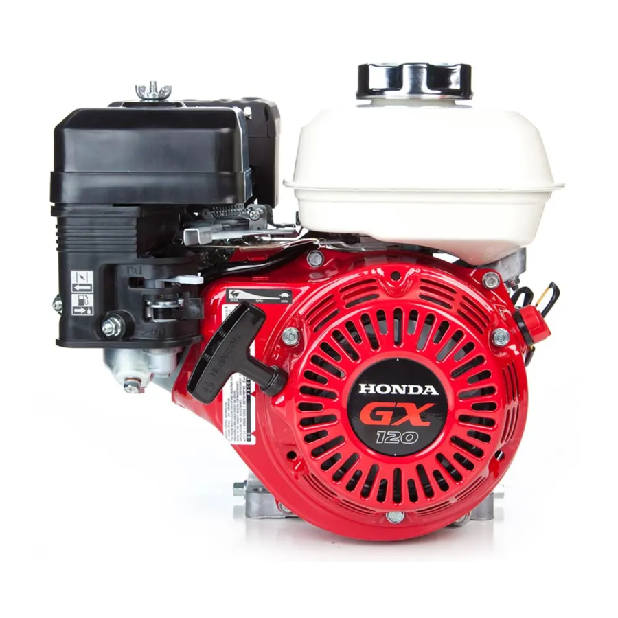
Honda GX120 Assembly Information
Hide thumbs
Also See for GX120:
- Owner's manual (65 pages) ,
- Tech manual (21 pages) ,
- Quick reference manual (3 pages)
Advertisement
Quick Links
PISTON RING
REASSEMBLY:
· Install all rings with the markings facing upward.
· Be sure that the top and second rings are not interchanged.
· Check that the rings rotate smoothly after installation.
· Space the piston ring end gaps 120 degrees apart, and
do not align the gaps with the piston pin bore.
· Space the oil ring side rail end gaps at least 10 mm (0.4 in)
apart. Coat the oil ring with oil after assembly.
TOP RING
CONNECTING
(CHROME FACED)
ROD
SECOND RING
REASSEMBLY:
(BLACK FACED)
connecting rod with the
long end toward the
OIL RING
triangle-marked side of
(COMBINATION RINGS)
the piston.
CRANKCASE COVER/CRANKSHAFT/PISTON
PISTON
REASSEMBLY:
Install with the
triangle mark
toward the
pushrod hole.
TRIANGLE MARK
PUSH ROD HOLE
OIL SEAL 22 x 35 x 6 mm (GX120)
25 x 41 x 6 mm
(GX160/GX200)
GOVERNOR DRIVE
GEAR
GREAS
CRANKCASE
OIL DRAIN
BOLT
18 N·m
(1.8 kgf·m,
13 lbf·ft)
DRAIN BOLT WASHER
Replace.
CONNECTING ROD BOLT
12 N·m (1.2 kgf·m, 9 lbf·ft)
CONNECTING ROD CAP
REASSEMBLY:
Install with the oil dipper toward the camshaft and the
ribs on the cap and connecting rod are aligned.
GX120 ·GX160 ·GX200 Engine Assembly Information
PISTON
MARKING
TOP RING (CHROME FACED)
SECOND RING (BLACK FACED)
OIL RING (COMBINATION RINGS)
PISTON
PISTON PIN CLIP
REASSEMBLY:
Install by setting one end of the clip in
PISTON PIN
the piston groove, holding the other
end with long-nosed pliers, and
rotating the clip in.
Do not align the end gap of the clip
with the cutout in the piston pin bore.
Install the
VALVE LIFTER
CAMSHAFT
REASSEMBLY:
REASSEMBLY:
・With the crankshaft in place, align the
Install the lifters
immediately before
timing punch mark on the cam gear with
the punch mark on the crankshaft gear.
installing the camshaft.
・Before installing, inspect for worn and
weakened springs and check that the
decompressor weight moves smoothly.
PUNCH MARKS
PUNCH MARKS
CRANKCASE
COVER
12 N·m (1.2 kgf·m, 9 lbf·ft)
GASKET
Do not reuse.
24 N·m (2.4 kgf·m, 17 lbf·ft)
OIL SEAL
22 x 41 x 6 mm (GX120)
25 x 41 x 6 mm (GX160/GX200)
BALL
BEARING
TIMING GEAR
CRANKSHAFT
REASSEMBLY:
Push in until the bearing touches
the crankcase. Be careful not to
damage the oil seal.
CRANKCASE COVER
See the shop manual for additional information.
VALVE SPRING RETAINER
GX120/GX160:
DISASSEMBLY:
Push down and slide the retainer to the side, so the valve
stem slips through the hole at the side of the retainer.
REASSEMBLY:
The exhaust valve retainer has a larger center recess than
the intake valve retainer so it can accept the valve rotator.
NOTICE:
Do not remove the valve spring retainers while the cylinder
head is installed, or the valves will drop into the cylinder.
VALVE ROTATOR (Exhaust valve only)
NOTICE:
If the valve rotator is not installed, the
exhaust valve may drop into the cylinder
CLIP
when starting the engine.
ROCKER ARM PIVOT (2)
CUT-OUT
ROCKER ARM
PIVOT LOCK NUT (2)
10 N·m (1.0 kgf·m, 7 lbf·ft)
ROCKER ARM (2)
REASSEMBLY:
Before installing, check for wear on the surfaces which contact
the pivot bolt, the push rod, and the rocker arm pivot.
INTAKE VALVE
REASSEMBLY:
· Do not interchange with the exhaust valve.
Valve head diameter: Intake: 25 mm (0.98 in) Exhaust: 24 mm (0.94 in)
· Be careful not to damage the valve stem seal when installing.
CYLINDER HEAD
6 x 28 (GX120)
8 x 55 (4) (GX120), 8 x 60 (4) (GX160/GX200)
24 N·m (2.4 kgf·m, 17 lbf·ft)
8 x 32 (GX160/GX200)
REMOVAL/INSTALLATION:
Loosen and tighten the
bolts in a crisscross pattern
in 2-3 steps.
CYLINDER HEAD
REMOVAL/INSTALLATION:
· Before installation, remove any carbon deposits
from the combustion chamber and inspect the
GREAS
valve seats.
· Measure the cylinder compression after reassembly.
CYLINDER HEAD/VALVES
CYLINDER HEAD
VALVE GUIDE (2)
VALVE SPRING (2)
ROCKER ARM PIVOT BOLT (2)
Refer to the above for information not shown below.
GX200:
VALVE STEM SEAL (Intake valve only)
Replace with a new one
when reassembling.
GOVERNOR WEIGHT
GASKET
REASSEMBLY:
Be sure
to install the governor
Do not reuse.
weight before installing
the crankshaft.
CLIP
REASSEMBLY:
Insert firmly
into the shaft
groove.
DOWEL PINS
CYLINDER BARREL
10 mm NUT
Green ( To side plate)
Yellow ( To engine switch)
EXHAUST VALVE
REASSEMBLY:
・Before installation, remove carbon deposits
and inspect the valve.
・Do not interchange with the intake valve.
VALVE HEAD DIAMETER
GX120: IN: 22 mm (0.87 in)
EX: 19 mm (0.75 in)
GX160: IN: 25 mm (0.98 in)
EX: 24 mm (0.94 in)
INTAKE VALVE
PUSH ROD (2)
REASSEMBLY:
Check both ends for wear,
and check the rod for
straightness.
Be sure the rod ends are
firmly seated in the lifters.
24 N·m (2.4 kgf·m, 17 lbf·ft)
GOVERNOR
WASHER
GOVERNOR SLIDER
REASSEMBLY:
WASHER (2)
Install inside
the case.
LOCK PIN
GOVERNOR
REASSEMBLY:
ARM SHAFT
The lock pin must be
installed with the
straight side of the pin
against the groove in
the shaft.
6 x 12 (2)
OIL LEVEL SWITCH
O-RING
REASSEMBLY:
Install firmly in the groove.
© Honda Motor Co., Ltd. 2009
Advertisement


