Table of Contents
Advertisement
Quick Links
Specification
n RADIO
Frequency range
FM
AM
n CD PLAYER
Sampling frequency
Decoding
Beam source
No. of channels
Wow and flutter
D/A converter
n TAPE RECORDER
Track system
Monitor system
Recording system
Erasing system
Frequency range
Normal position
n GENERAL
Speakers
87.50-108.00 MHz (50 kHz steps)
522-1629 kHz (9 kHz steps)
520-1630 kHz (10 kHz steps)
44.1 kHz
16 bit linear
Semiconductor laser (wavelength
780 nm)
2 channel, stereo
Below measurable limit
MASH (1 bit DAC)
Stereo
Variable sound monitor
AC bias
Multi Pole magnet
50-14000 Hz
8 cm 5.4Ω x 2
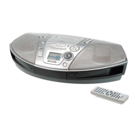
Portable Stereo CD System
RX-ES29GC
RX-ES29GS
RX-ES29GT
Colour
(S)..........Silver Type
Jacks
Output
Power requirement (For GC/GS)
AC
Power consumption
Power requirement (For GT)
AC
Power consumption
Battery
Memory backup for
computer/clock
Dimensions
Mass (For GC/GS)
Mass (For GT)
Power consumption in standby
mode (For GC/GS)
Power consumption in standby
mode (For GT)
Notes:
1. Specifications are subject to change without notice.
2. Mass and dimensions are approximate.
© 2005 Matsushita Electric Industrial Co. Ltd.. All
rights
reserved.
distribution is a violation of law.
Order No. MD0503060C3
Phones: 3.5 mm stereo (16-32Ω)
110-127 V / 220-240 V, 50/60 Hz
110 V, 60 Hz
12 V [Eight R20/LR20 (D, UM-1)
l Do not use rechargeable type batteries
6 V [Four R6/LR6 (AA, UM-3)
l Do not use rechargeable type batteries
529 mm (W) x 144 mm (H) x 276
4.4 kg without batteries
4.2 kg without batteries
3.0 W (117 V)
3.5W (240 V)
Unauthorized
copying
33 W
32 W
batteries]
batteries]
mm (D)
2.7 W
and
Advertisement
Table of Contents

Related Manuals for Panasonic RX-ES29GS


Summary of Contents for Panasonic RX-ES29GS
- Page 1 Order No. MD0503060C3 Portable Stereo CD System RX-ES29GC RX-ES29GS RX-ES29GT Colour (S)..Silver Type Specification n RADIO Jacks Frequency range Output Phones: 3.5 mm stereo (16-32Ω) 87.50-108.00 MHz (50 kHz steps) Power requirement (For GC/GS) 522-1629 kHz (9 kHz steps) 110-127 V / 220-240 V, 50/60 Hz...
-
Page 2: Table Of Contents
RX-ES29GC / RX-ES29GS / RX-ES29GT CONTENTS Page Page 1 Safety Precautions 14.1. Self-diagnosis Function 1.1. GENERAL GUIDELINES 14.2. Setting of doctor mode 2 Caution for AC Mains Lead 15 Measurements and Adjustments 3 Before Use 15.1. Tuner Section 4 Before Repair and Adjustment 15.2. -
Page 3: Safety Precautions
RX-ES29GC / RX-ES29GS / RX-ES29GT 1 Safety Precautions 1.1. GENERAL GUIDELINES 1. When servicing, observe the original lead dress. If a short circuit is found, replace all parts which have been overheated or damaged by the short circuit. 2. After servicing, ensure that all the protective devices such as insulation barriers, insulation papers shields are properly installed. -
Page 4: Caution For Ac Mains Lead
RX-ES29GC / RX-ES29GS / RX-ES29GT 2 Caution for AC Mains Lead... -
Page 5: Before Use
RX-ES29GC / RX-ES29GS / RX-ES29GT 3 Before Use Be sure to disconnect the mains cord before adjusting the voltage selector. Use a minus (-) screwdriver to set the voltage selector (on the rear panel) to the voltage setting for the area in which the unit will be used. -
Page 6: Precaution Of Laser Diode
RX-ES29GC / RX-ES29GS / RX-ES29GT 7 Precaution of Laser Diode CAUTION: This unit utilizes a class 1 laser. Invisible laser radiation is emitted from the optical pickup lens. When the unit is turned on: 1. Do not look directly into the pick up lens. -
Page 7: Handling Precautions For Traverse Deck
RX-ES29GC / RX-ES29GS / RX-ES29GT 8 Handling Precautions For Traverse Deck The laser diode in the traverse deck (optical pickup) may break down due to potential difference caused by static electricity of clothes or human body. So, be careful of electrostatic breakdown during repair of the traverse deck (optical pickup). -
Page 8: Accessories
RX-ES29GC / RX-ES29GS / RX-ES29GT 9 Accessories Note : Refer to Packing Materials & Accessories Parts List (Section 25.5) for the part number. Remote Control..1pc AC cord..1 pc (For AC cord..1 pc (For AC cord..1 pc (For AC cord adaptor..1... -
Page 9: Operation Procedures
RX-ES29GC / RX-ES29GS / RX-ES29GT 10 Operation Procedures 10.1. Main unit... -
Page 10: Remote Control
RX-ES29GC / RX-ES29GS / RX-ES29GT 10.2. Remote control... -
Page 11: Information On Mp3
RX-ES29GC / RX-ES29GS / RX-ES29GT 11 Information on MP3... -
Page 12: Disassembly And Main Component Replacement Procedures And Operational Check
RX-ES29GC / RX-ES29GS / RX-ES29GT 12 Disassembly and Main Component Replacement Procedures and Operational Check “ATTENTION SERVICER” Some chassis components may be have sharp edges. Be careful when disassembly and servicing. 1. This section describes procedures for checking the operation of the major printed circuit boards and replacing the main components. -
Page 13: Checking Procedure For Each Major P.c.b
RX-ES29GC / RX-ES29GS / RX-ES29GT 12.3. Checking Procedure for each major P.C.B. 12.3.1. Disassembly of Top Cabinet Unit. Step 3: Flip up the handle as arrow direction shown. Step 1: Remove 10 screws. Step 2: Remove 2 screws. Step 4: Use a screw driver and insert into the hole. Slide the screw driver to the direction shown to open the cassette panel. - Page 14 RX-ES29GC / RX-ES29GS / RX-ES29GT Step 5: Cassette panel will automatically open. Step 8: Flip the top cabinet over as arrow shown. Step 9: Detach the FFC wire (CP401). 12.3.2. Disassembly of Panel P.C.B. Follow (step 1) to (step 9) of item 12.3.1.
- Page 15 RX-ES29GC / RX-ES29GS / RX-ES29GT Step 5: Release 2 catches. Step 3: Remove the front panel from top cabinet as arrow shown. Step 6: Flip over the control button unit with the Panel P.C.B. as arrow shown. Step 4: Remove 6 screws.
-
Page 16: Disassembly Of Deck Mechanism
RX-ES29GC / RX-ES29GS / RX-ES29GT 12.3.3. Disassembly of Speakers. Follow (step 1) to (step 9) of item 12.3.1. Follow (step 1) to (step 10) of item 12.3.2. Step 8: Release 6 catches. Step 1: Remove 8 screws. Step 9: Remove the Panel P.C.B. as arrow shown. - Page 17 RX-ES29GC / RX-ES29GS / RX-ES29GT Step 1: Remove 4 screws. Step 3: Release the connector (CP1450) to remove the deck mechanism. 12.3.5. Disassembly of Main, Standby LED, Power On and Sensor P.C.B. Follow (step 1) to (step 9) of item 12.3.1.
- Page 18 RX-ES29GC / RX-ES29GS / RX-ES29GT Step 4: Remove 2 screws. Step 5: Release all the connectors (CP501, CP402 & CP801). Step 7: Release the Sensor P.C.B. as arrow shown. Step 8: Remove the Main P.C.B. as arrow shown. 12.3.6. Disassembly of Battery and Power P.C.B.
- Page 19 RX-ES29GC / RX-ES29GS / RX-ES29GT Step 3: Remove the Battery P.C.B. as arrow shown. Step 5: Remove the transformer together with battery P.C.B. and Power P.C.B. as arrow shown. 12.3.7. Disassembly of CD Loading Mechanism. Follow (step 1) to (step 9) of item 12.3.1.
- Page 20 RX-ES29GC / RX-ES29GS / RX-ES29GT Step 2: Remove the CD Loading Mechanism as arrow shown. Step 1: Remove the cassette open spring. 12.3.8. Replacement of Cassette Panel. Follow (step 1) to (step 9) of item 12.3.1. Step 2: Push the cassette panel slowly to the right.
-
Page 21: Procedures For Replacing Pinch Roller And Head Block (Deck Mechanism Unit)
RX-ES29GC / RX-ES29GS / RX-ES29GT Step 3: Push the cassette panel slowly to the left using a screw driver. Caution: Be careful of using/exerting strong forces. 12.5. Procedures for Replacing Motor, Capstan Belt A, Capstan Belt B, and Winding Belt (Deck Mechanism Unit) Step 4: Remove the cassette panel from top cabinet as arrow Follow (step 1) to (step 9) of item 12.3.1. - Page 22 RX-ES29GC / RX-ES29GS / RX-ES29GT...
-
Page 23: Procedures For Replacing Parts On Deck Mechanism Pcb
RX-ES29GC / RX-ES29GS / RX-ES29GT Follow (step 1) to (step 3) of item 12.3.4. 12.7. Procedures of Replacing Traverse Base (Unit), Driving Gear, and Cam Gear (CD Mechanism Unit) 12.7.1. Disassembly of the Disc Tray. Follow (step 1) to (step 9) of item 12.3.1. - Page 24 RX-ES29GC / RX-ES29GS / RX-ES29GT...
- Page 25 RX-ES29GC / RX-ES29GS / RX-ES29GT...
-
Page 26: Procedures For Replacing Optical Pickup (Cd Mechanism Unit)
RX-ES29GC / RX-ES29GS / RX-ES29GT 12.8. Procedures for Replacing Optical Pickup (CD Mechanism Unit) Follow (step 1) to (step 9) of item 12.3.1. Follow (step 1) to (step 3) of item 12.3.4. Follow (step 1) to (step 8) of item 12.3.5. -
Page 27: Procedures For Replacement Traverse Gear A And Traverse Gear B (Cd Mechanism Unit)
RX-ES29GC / RX-ES29GS / RX-ES29GT 12.9. Procedures for Replacement Traverse Gear A and Traverse Gear B (CD Mechanism Unit) Follow (step 1) to (step 9) of item 12.3.1. Follow (step 1) to (step 3) of item 12.3.4. Follow (step 1) to (step 8) of item 12.3.5. - Page 28 RX-ES29GC / RX-ES29GS / RX-ES29GT...
-
Page 29: Procedure For Checking Of The Major P.c.b
RX-ES29GC / RX-ES29GS / RX-ES29GT 13 Procedure for checking of the major P.C.B. 13.1. Checking the Main P.C.B., Panel P.C.B., Deck Mechanism P.C.B., CD Servo P.C.B., Battery P.C.B., Sensor P.C.B., Power-On P.C.B., Power and Standby LED P.C.B. Preparation Follow items 12.3.1. to 12.3.7. of Disassembly Procedure. -
Page 30: Self Diagnostic Function
RX-ES29GC / RX-ES29GS / RX-ES29GT 14 Self Diagnostic Function 14.1. Self-diagnosis Function 14.1.1. Entering into self-diagnosis mode 1. Ensure there is no cassette tape in the deck unit. 2. Switch to CD function. 3. Press and hold the [CD/TAPE STOPn] key of the main set for more than 2 seconds. While pressing this key, press the FF key on the main set for another 2 seconds to enter into the Self-Diagnosis mode. - Page 31 RX-ES29GC / RX-ES29GS / RX-ES29GT Error code Possible symptom Description of problem Power supply cut · During operation, when PDET switches to OFF (PDET - 1.534V) due to fall of power supply voltage fall, the power supply will be automatically switched OFF.
-
Page 32: Setting Of Doctor Mode
RX-ES29GC / RX-ES29GS / RX-ES29GT Figure 14-2 14.2. Setting of doctor mode 1. Switch to CD mode. (Ensure no disc is inserted) 2. To enter Doctor mode, press and hold [TAPE/CD STOPn] key at the main unit, followed by [4] & [7] on remote control. - Page 33 RX-ES29GC / RX-ES29GS / RX-ES29GT 4. However, if the EEPROM was not detected, it will not display the EEPROM’s checksum information. The LCD will display micro- p version number (as shown below) for 1 sec and return to normal Doctor Mode display.
- Page 34 RX-ES29GC / RX-ES29GS / RX-ES29GT Figure 14-3 3. After a few times, the LCD shall display as below: Special Note: Due to certain reasons, when the following conditions occur, the aging will stop but the count value shall be maintained: ·...
- Page 35 RX-ES29GC / RX-ES29GS / RX-ES29GT Figure 14-4 3. After a few times, the LCD will display as shown below: Special Note : Due to certain reasons, when the following conditions occur, the aging will stop but the count value shall be maintained: ·...
- Page 36 RX-ES29GC / RX-ES29GS / RX-ES29GT Figure 14-5 3. After a few times, the LCD will display as shown below: Special Note : Due to certain reason, when the following conditions occur, the aging will stop but the count value shall be maintained: ·...
- Page 37 RX-ES29GC / RX-ES29GS / RX-ES29GT Example of LCD Display:...
-
Page 38: Measurements And Adjustments
RX-ES29GC / RX-ES29GS / RX-ES29GT 15 Measurements and Adjustments 15.1. Tuner Section READ CAREFULLY BEFORE ATTEMPTING ALIGNMENT 1. Set selector switch to AM or TAPE. 2. Set volume level to 40. 3. Output of signal generator should be no higher than necessary to obtain an output reading. -
Page 39: Deck Section
RX-ES29GC / RX-ES29GS / RX-ES29GT 15.2. Deck Section · HEAD AZIMUTH ALIGNMENT Test Tape Indicator (Electronic Adjustment Remarks Voltmeter or oscilloscope) QZZCFM Headphone Jack Azimuth Screw 1. Insert a test tape (QZZFCM) and start playback in the forward direction. (8 kHz, -20 dB) (Shown in Fig. - Page 40 RX-ES29GC / RX-ES29GS / RX-ES29GT...
-
Page 41: Voltage Measurement
RX-ES29GC / RX-ES29GS / RX-ES29GT 16 Voltage Measurement Note: · Indicated voltage values are the standard values for the unit measured by the DC electronic circuit tester (high-impedance) with the chassis taken as standard. Therefore, there may exist some errors in the voltage values, depending on the internal impedance of the DC circuit tester. -
Page 42: Main P.c.b
RX-ES29GC / RX-ES29GS / RX-ES29GT 16.2. Main P.C.B. - Page 43 RX-ES29GC / RX-ES29GS / RX-ES29GT...
-
Page 44: Waveform Chart
RX-ES29GC / RX-ES29GS / RX-ES29GT 17 Waveform Chart CP402 PIN 4 CP402 PIN 5 CP402 PIN 6 CP402 PIN 7 CD PLAY CD PLAY CD PLAY CD PLAY 3.56Vp-p (10msec.div) 3.44Vp-p (10msec.div) 3.28Vp-p (10msec.div) 3.40Vp-p (10msec.div) CP402 PIN 8 IC801 PIN 17... -
Page 45: Notes Of Schematic Diagram
RX-ES29GC / RX-ES29GS / RX-ES29GT 18 Notes of Schematic Diagram (All schematic diagrams may be modified at any time with the development of new technology.) Notes: S701 : REST SWITCH S780 : OPEN SWITCH S901 : VOL+ SWITCH S902 :... -
Page 46: Schematic Diagram
RX-ES29GC / RX-ES29GS / RX-ES29GT 19 Schematic Diagram 19.1. CD SERVO CIRCUIT SCHEMATIC DIAGRAM - 1 CD SERVO CIRCUIT : +B SIGNAL LINE : CD-DA SIGNAL LINE OPTICAL PICKUP UNIT C701 6.3V33 R701 Q701 B1ADCF000001 CN701 LASER POWER DRIVE Vref... - Page 47 RX-ES29GC / RX-ES29GS / RX-ES29GT SCHEMATIC DIAGRAM - 2 : CD-DA SIGNAL LINE CD SERVO CIRCUIT : +B SIGNAL LINE : CD SIGNAL LINE C703 C724 C723 C704 C755 6.3V100 6.3V220 C727 R717 50V1 C725 1000P C726 C728 R718 R711...
-
Page 48: Main Circuit And Power On Circuit
RX-ES29GC / RX-ES29GS / RX-ES29GT 19.2. MAIN CIRCUIT and POWER ON CIRCUIT SCHEMATIC DIAGRAM-3 : PLAYBACK SIGNAL LINE MAIN CIRCUIT : FM/AM SIGNAL LINE : RECORD SIGNAL LINE : +B SIGNAL LINE R803 150K L801 G0C2R2KA0029 R804 R802 R801 100K... - Page 49 RX-ES29GC / RX-ES29GS / RX-ES29GT D805 SCHEMATIC DIAGRAM-4 LNW9A8BYBZ POWER ON LED POWER ON CIRCUIT MAIN CIRCUIT : +B SIGNAL LINE W801 COM0 SEG25 COM1 SEG26 SEG27 COM2 COM3 SEG28 VLC3 VLC2 VLC1 ECLK EDATA IC801 MBP1 D803,D804 MN101C74GAA2 MBP2...
- Page 50 RX-ES29GC / RX-ES29GS / RX-ES29GT SCHEMATIC DIAGRAM-5 : +B SIGNAL LINE : CD SIGNAL LINE : PLAYBACK SIGNAL LINE MAIN CIRCUIT : FM/AM SIGNAL LINE : RECORD SIGNAL LINE : MAIN SIGNAL LINE Z801 L5ACAGD00019 R101 R213 R113 R234 R134...
- Page 51 RX-ES29GC / RX-ES29GS / RX-ES29GT SCHEMATIC DIAGRAM-6 : +B SIGNAL LINE MAIN CIRCUIT : MAIN SIGNAL LINE R120 R130 C231 D201 16V330 B0BA7R500006 C131 D101 16V330 B0BA7R500006 R111 R110 C103 C102 R124 16V10 0.068 Q102 C111 C120 R119 0.022 0.015 2.2K...
- Page 52 RX-ES29GC / RX-ES29GS / RX-ES29GT SCHEMATIC DIAGRAM-7 : +B SIGNAL LINE MAIN CIRCUIT : MAIN SIGNAL LINE C301 R302 25V4700 C303 16V22 STAND BY VCC1 VCC2 SIGNAAL +OUT1 MUTE R303 4.7K GND1 C304 -OUT1 16V47 IC301 +OUT2 GND2 -OUT2 C219...
- Page 53 RX-ES29GC / RX-ES29GS / RX-ES29GT SCHEMATIC DIAGRAM-8 : +B SIGNAL LINE MAIN CIRCUIT : MAIN SIGNAL LINE : CD SIGNAL LINE C121 16V10 R121 R221 C221 50V10 HEADPHONE C122 C222 R339 50V2.2 50V2.2 R340 100K Q316 JK301 Q317 B1AAGF000008 R341...
- Page 54 RX-ES29GC / RX-ES29GS / RX-ES29GT SCHEMATIC DIAGRAM-9 MAIN CIRCUIT : +B SIGNAL LINE : CD SIGNAL LINE C101 1000P C201 CD L 1000P A_GND CD_R L400 G0A200D00002 CD_3.3V D3.3V LD_SW/CLDCK C414 1000P D_GND CD_7.5V CD7.5V IC401 C419 C418 C421 C423...
-
Page 55: Main (Tuner) Circuit
RX-ES29GC / RX-ES29GS / RX-ES29GT 19.3. MAIN (TUNER) CIRCUIT SCHEMATIC DIAGRAM - 10 : FM/AM SIGNAL LINE : AM SIGNAL LINE MAIN (TUNER) CIRCUIT : FM OSC SIGNAL LINE : +B SIGNAL LINE : AM OSC SIGNAL LINE 0.022 1000P... - Page 56 RX-ES29GC / RX-ES29GS / RX-ES29GT SCHEMATIC DIAGRAM - 11 : FM/AM SIGNAL LINE MAIN (TUNER) CIRCUIT : +B SIGNAL LINE 3.9K 100P 1000P 330P C1CA00000198 PLL IC H0A720400003 0.01 1000P 1000P 1000P 2.2K 50V2.2 4.7K 2200P 0.01 G0C101KA0029 3.3K 1000P...
-
Page 57: Main (Deck) Circuit And Deck Mechanism Circuit
RX-ES29GC / RX-ES29GS / RX-ES29GT 19.4. MAIN (DECK) CIRCUIT and DECK MECHANISM CIRCUIT SCHEMATIC DIAGRAM-12 : PLAYBACK SIGNAL LINE MAIN (DECK) CIRCUIT : +B SIGNAL LINE : +B SIGNAL LINE Q1103, Q1104 C1107 50V1 B1DEDQ000004 C1108 R1108 HEAD SELECT 820P 3.9K... - Page 58 RX-ES29GC / RX-ES29GS / RX-ES29GT SCHEMATIC DIAGRAM-13 : PLAYBACK SIGNAL LINE MAIN (DECK) CIRCUIT : +B SIGNAL LINE : +B SIGNAL LINE Q1101, Q1201 B1DEDQ000004 SWITCH R1204 R1104 Q1201 Q1101 R1002 4.7K Q1000 KRC119MTA SWITCH Q1000 Q1102 Q1202 R1207 TAPE_REC_Rch...
-
Page 59: Panel Circuit, Standby Led Circuit, Battery
RX-ES29GC / RX-ES29GS / RX-ES29GT 19.5. PANEL CIRCUIT, STANDBY LED CIRCUIT, BATTERY CIRCUIT, POWER CIRCUIT and SENSOR CIRCUIT SCHEMATIC DIAGRAM-14 STANDBY LED SENSOR : +B SIGNAL LINE CIRCUIT CIRCUIT : MAIN SIGNAL LINE D401 Z401 SLR325VRT31 STANDBY LED W401 B3RAB0000046... -
Page 60: Printed Circuit Board
RX-ES29GC / RX-ES29GS / RX-ES29GT 20 Printed Circuit Board 20.1. CD SERVO P.C.B. CD SERVO P.C.B (REPV0039A) C755 TP51 C727 C718 TP19 C725 TP16 C726 R711 J711 TP23 TP50 C716 J722 C728 TP17 C702 TP18 C705 TP87 C729 C706 TP13... -
Page 61: Main P.c.b
RX-ES29GC / RX-ES29GS / RX-ES29GT 20.2. MAIN P.C.B. MAIN P.C.B (REPV0043C...GC/GS) (REPV0043D...GT) HEADPHONE TP21 Q316 Q317 R327 R339 Q309 W351 D314 Q311 C314 W330 D308 Q308 JK301 R121 C315 C219 R335 IC301 D311 Q314 W407 W380 R226 Q312 Q313 W352... - Page 62 RX-ES29GC / RX-ES29GS / RX-ES29GT TELESCOPIC ANTENNA R339 W351 D314 Q311 C315 R335 D311 Q314 2 Q313 R337 R336 R338 R306 Q315 D301 C309 C305 IC303 IC302 Q301 C330 C331 W388 W375 W349 W348 W336 W385 W386 W387 W337 W339...
-
Page 63: Panel P.c.b. And Deck Mechanism P.c.b
RX-ES29GC / RX-ES29GS / RX-ES29GT 20.3. PANEL P.C.B. and DECK MECHANISM P.C.B. PANEL P.C.B (REPV0045A) S916 PLAY/REC S909 R910 S914 CD REC S910 S908 S912 CLOCK MODE R912 /TIMER CD PLAY/PAUSE TUNER BAND TAPE R904 R914 R908 R911 R913 S911... -
Page 64: Standby Led P.c.b, Battery P.c.b, Power On
RX-ES29GC / RX-ES29GS / RX-ES29GT 20.4. STANDBY LED P.C.B, BATTERY P.C.B, POWER ON P.C.B and SENSOR P.C.B STANDBY LED P.C.B BATTERY P.C.B (REPV0043C...GC/GS) (REPV0043C...GC/GS) (REPV0043D...GT) (REPV0043D...GT) 12V (1.5V X 8 BATTERIES) D-TYPE, UM-1, R20/LR20 D401 W401 FP501 W505 W504 POWER ON P.C.B (REPV0043C...GC/GS) -
Page 65: Power
RX-ES29GC / RX-ES29GS / RX-ES29GT 20.5. POWER P.C.B. POWER P.C.B (REPV0043C...GC/GS) H502 CP501 /W502 R501 F501 250V T4AL FH501 FH502 T501 TRANSFORMER C501 JK501 W501 AC IN 5-BATT 4-AC 110V-127V 3-COM 220V-240V 50/60Hz W502 SW502 VOLTAGE SELECTOR CAUTION RISK OF ELECTRIC SHOCK AC VOLTAGE LINE. -
Page 66: Wiring Connection Diagram
RX-ES29GC / RX-ES29GS / RX-ES29GT 21 Wiring Connection Diagram SOLDER SIDE H502/W502 CP501 POWER P.C.B SENSOR P.C.B T501 TRANSFORMER JK501 W403 Z401 AC IN 110V-127V SENSOR 220V-240V 50/60Hz (GC/GS) 110V 60Hz (GT) SOLDER SIDE PANEL P.C.B SOLDER SIDE H901 Z901... - Page 67 RX-ES29GC / RX-ES29GS / RX-ES29GT 12V (1.5V X 8 BATTERIES) D-TYPE, UM-1, R20/LR20 DECK MECHANISM P.C.B BATTERY P.C.B 9 ..1 CS971 SOLDER SIDE W502 SOLDER SIDE SOLENOID R/P Head SOLDER SIDE 6V (1.5V X 4 BATTERIES)
-
Page 68: Type Illustration Of Ic 痴, Transistors And Diodes
RX-ES29GC / RX-ES29GS / RX-ES29GT 22 Type Illustration of IC’s, Transistors and Diodes C1BA00000395 (24P) LA4663 (14P) MN6627953HB (80P) C0CAABC00007 C1BB00000732 (32P) MN101C74GAA2 (100P) C1CA00000198 (22P) C0JBAZ001229 (14P) BA5948FPE2 (28P) No.1 C1AA00000612 (5P) KTC3199GRTA C0CAADC00031 (3P) CNB13030R2AU AN7317 (16P) KTA1270YTA... -
Page 69: Terminal Function Of Ic 痴
RX-ES29GC / RX-ES29GS / RX-ES29GT 23 Terminal Function Of IC’s 23.1. IC801 (MN101C74GAA2): Terminal Name Function Microprocessor ASP_DATA ASP SERIAL DATA OUTPUT PCONT POWER CONTROL OUTPUT Terminal Name Function REM_STBY AC IN DETECTION NO CONNECTION COM0 LCD COMMON OUTPUT NO CONNECTION... -
Page 70: Troubleshooting Flowchart (Cd Section Circuit)
RX-ES29GC / RX-ES29GS / RX-ES29GT 24 Troubleshooting Flowchart (CD Section Circuit) - Page 71 RX-ES29GC / RX-ES29GS / RX-ES29GT...
-
Page 72: Parts Location And Replacement Parts List
RX-ES29GC / RX-ES29GS / RX-ES29GT 25 Parts Location and Replacement Parts List Notes: · Important safety notice: Components identified by mark have special characteristics important for safety. Furthermore, special parts which have purposes of fire-retardant (resistors), high-quality sound (capacitors), low noise (resistors), etc are used. -
Page 73: Deck Mechanism (Raa4401-1V)
RX-ES29GC / RX-ES29GS / RX-ES29GT 25.1. Deck Mechanism (RAA4401-1V) 25.1.1. Deck Mechanism Parts Location... - Page 74 RX-ES29GC / RX-ES29GS / RX-ES29GT 25.1.2. Deck Mechanism Parts List Ref. Part No. Part Name & Description Remarks CASSETTE DECK RED0062 HEAD BLOCK UNIT RDG0300 REEL BASE GEAR RDG0301 WINDING RELAY GEAR RDK0026-4 MAIN GEAR RDV0033-4 WINDING BELT RDV0064 CAPSTAN BELT...
-
Page 75: Cd Loading Mechanism
RX-ES29GC / RX-ES29GS / RX-ES29GT 25.2. CD Loading Mechanism 25.2.1. CD Loading Mechanism Parts Location... - Page 76 RX-ES29GC / RX-ES29GS / RX-ES29GT 25.2.2. CD Loading Mechanism Parts List Ref. Part No. Part Name & Description Remarks TRAVERSE DECK RAE0157Z-V CT 130MP TRV RDG0455 TRAVERSE GEAR (A) RDG0456 TRAVERSE GEAR (B) RFKNCT100 TRAVERSE BASE ASS’Y 304-1 RDG0457 LOAD GEAR (A)
-
Page 77: Cabinet Part List
RX-ES29GC / RX-ES29GS / RX-ES29GT 25.3. Cabinet Part List 25.3.1. Cabinet Parts Location... - Page 78 RX-ES29GC / RX-ES29GS / RX-ES29GT 25.3.2. Cabinet Part List Ref. Part No. Part Name & Description Remarks CABINET AND CHASSIS RFKKXES29EGS UPPER CABINET ASS’Y RKWX0140-Q LCD PANEL RFKJXES29GCS BOTTOM CABINET ASS’Y [M]GC RFKJXES29GSS BOTTOM CABINET ASS’Y [M]GS RFKJXES29GTS BOTTOM CABINET ASS’Y...
-
Page 79: Electrical Part List
RX-ES29GC / RX-ES29GS / RX-ES29GT 25.4. Electrical Part List Ref. Part No. Part Name & Description Remarks Ref. Part No. Part Name & Description Remarks Printed Circuit Board Q1402 KRC119MTA TRANSISTOR Q1403 KRC119MTA TRANSISTOR REPV0039A CD SERVO P.C.B. [M] RTL... - Page 80 RX-ES29GC / RX-ES29GS / RX-ES29GT Ref. Part No. Part Name & Description Remarks Ref. Part No. Part Name & Description Remarks FUSE PROTECTOR CONNECTORS CN701 RJS2A8616 16P FPC CONNECTOR FP501 K5G402A00025 FUSE PROTECTOR CN702 RJS2A7717 17P FFC CONNECTOR HOLDERS CP401...
- Page 81 RX-ES29GC / RX-ES29GS / RX-ES29GT Ref. Part No. Part Name & Description Remarks Ref. Part No. Part Name & Description Remarks R122 ERD2FCVJ4R7T 4.7 1/4W R406 ERDS2TJ332T 3.3K 1/4W R123 ERDS2TJ471T 470 1/4W R407 ERDS2TJ332T 3.3K 1/4W R124 ERDS2TJ683T 68K 1/4W...
- Page 82 RX-ES29GC / RX-ES29GS / RX-ES29GT Ref. Part No. Part Name & Description Remarks Ref. Part No. Part Name & Description Remarks R836 ERDS2TJ102T 1K 1/4W R1405 D0AE473JA048 47K 1/4W R837 D0AE473JA048 47K 1/4W R1406 D0AE473JA048 47K 1/4W R839 ERDS2TJ334T 330K 1/4W...
- Page 83 RX-ES29GC / RX-ES29GS / RX-ES29GT Ref. Part No. Part Name & Description Remarks Ref. Part No. Part Name & Description Remarks C114 ECQV1H104JL3 0.1 50V C422 F1D1H221A012 220P 50V C118 F1D1H102A012 1000P 50V C423 F1D1H221A012 220P 50V C119 ECQB1H104JF3 0.1 50V...
- Page 84 RX-ES29GC / RX-ES29GS / RX-ES29GT Ref. Part No. Part Name & Description Remarks C901 F1D1H101A012 100P 50V C902 F1D1H101A012 100P 50V C1001 ECA1CAK470XB 47 16V C1101 F1D1H101A012 100P 50V C1102 F1D1C122A010 1200P 16V C1103 F1D1H101A012 100P 50V C1104 F1C1C393A024 0.039 16V...
-
Page 85: Packaging Materials & Accessories Parts List
RX-ES29GC / RX-ES29GS / RX-ES29GT 25.5. Packaging Materials & Accessories Parts List Ref. Part No. Part Name & Description Remarks Ref. Part No. Part Name & Description Remarks PACKING MATERIALS K2CQ2CA00002 AC CORD [M]GC RJA0053-3X AC CORD [M]GS RPGV0166 PACKING CASE...