Table of Contents
Advertisement
Quick Links
Bell System (Telephones) Ltd.
tabellet
2-72 Multi Way
Video Door Entry System
With
Hands-free Colour Apartment Stations
Installation & Operation Manual
This manual applies to the following: -
BFD2-72 Way Door controller –
Version 1 Builds 1
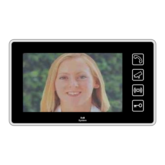
tabellet Colour Apartment Station –
Version 1 Build 1 to 2
BS Colour Videophone –
Version 2 Builds 1 to 3
XL5-BS Audio Phone –
Version 1 Build 1
BSC4 Video Controller –
Version 2 Build 7
PD-307 Issue 2
June 2017
Advertisement
Table of Contents

Related Manuals for Bell System 2-72 Multi Way


Summary of Contents for Bell System 2-72 Multi Way
- Page 1 Bell System (Telephones) Ltd. tabellet 2-72 Multi Way Video Door Entry System With Hands-free Colour Apartment Stations Installation & Operation Manual This manual applies to the following: - BFD2-72 Way Door controller – Version 1 Builds 1 tabellet Colour Apartment Station –...
- Page 2 tabellet Apartment Station 2-72 Way System tabellet Apartment Station BFD8 controller BSC4 controller XL5-BS audiophone BS videophone BS Deskphone PD-307 Issue 2 Installation and Operating Manual Page 2 of 48...
-
Page 3: Table Of Contents
tabellet Apartment Station 2-72 Way System TABLE OF CONTENTS TABLE OF CONTENTS ...................... 3 INTRODUCTION ......................... 4 ........................4 ESCRIPTION ......................... 4 EATURES BASIC SYSTEM OPERATION .................... 6 DESIGN CONSIDERATIONS ....................9 ......................... 9 QUIPMENT ..........................9 PTIONS ..................11 OWER UPPLY EQUIREMENTS... -
Page 4: Introduction
tabellet Apartment Station 2-72 Way System Introduction Description A tabellet video door entry system consists of a door panel, positioned at the entrance of a building, video apartment stations, placed inside of the building for the convenience of the occupants and a power supply and controller which are usually located inside an electrical cupboard. - Page 5 tabellet Apartment Station 2-72 Way System tabellet Colour Apartment Station Mode Handset Camera Sounder Idle Idle Mute Active Idle Door Open Idle Mute and Door Open Off Ringing Blue Flash Blue Flash Off Muted Ring Blue Flash Blue Flash Red Video Answer or CCTV Blue Flash Yellow Green Flash...
-
Page 6: Basic System Operation
tabellet Apartment Station 2-72 Way System Basic System Operation Call sequence When the call button is pressed at the entrance panel the apartment station will ring and its blue pickup / view lamp will flash, highlighting the pickup and view symbols. The apartment station will continue to ring for up to 30 seconds or until the resident responds by touching the view symbol (see silent viewing below) or the pickup symbol. - Page 7 tabellet Apartment Station 2-72 Way System Call Privacy Once a call has been made from an entrance panel only the apartment station(s) which is / are ringing may answer the call. Once the call is answered another apartment station will not activate (including extensions of the active apartment station).
- Page 8 tabellet Apartment Station 2-72 Way System Multiple Entrances free The bell system allows multiple entrances to be catered for by the addition of a door controller and entrance panel for each entrance and additional power supplies. In a multiple entrance system an optional feature allows the resident to view the cameras at all the entrances with successive touches of the view symbol.
-
Page 9: Design Considerations
tabellet Apartment Station 2-72 Way System Design Considerations Equipment List A tabellet-n tabellet Video Kit (where n is the no of ways) comprises the following: - Model No Description N x tabellet Colour apartment station 1 x BFPn Vandal resistant panel with a BF-AMP speech unit, VR buttons and camera. - Page 10 tabellet Apartment Station 2-72 Way System Entrance Panel – Important Note Careful consideration should be given to the location of the entrance panel to ensure the best possible lighting conditions for the camera. In general strong back lighting of the subject (by the sun and sky) should be avoided, as the contrast between foreground and background may be too great for the camera.
-
Page 11: Power Supply Requirements
Note 2. The PS4 power supply has been specifically designed to operate with the high- surge requirements of the system. Bell System is unable to guarantee functionality or provide support for systems which use third party power supplies. - Page 12 tabellet Apartment Station 2-72 Way System The following table is a guide to how much equipment a PS4 power supply can safely and reliably feed, please contact technical support for other variations. Equipment 1 x PS4 can power Comments 4 x BSC4 video controllers with 1 tabellet 16 apartment station s directly powered.
-
Page 13: Cable Specification
(or greater) power cable as tabulated below. Cat5 cable has a known performance for the transmission of video signals, whilst telephone or alarm cables are not suitable. Bell System will be unable to offer any warranty or support for systems installed using incorrect cables. -
Page 14: Cable Distances
tabellet Apartment Station 2-72 Way System Cable Distances Video Controller to tabellet Apartment Station System Distance Cable Comments Single apartment station < 100m 1 x Cat5 per output or first < 300m 1 x Cat5 apartment station 2 x 1mm Single apartment station + <... -
Page 15: Installation & Commissioning
tabellet Apartment Station 2-72 Way System Installation & Commissioning Checklist The following checklist is a summary of what is required. Refer to the relevant pages for further details. ● Review the section headed ‘Safety Information’ on page 47. ● Ensure that ‘Design Considerations’ on page 9 have been understood. ●... - Page 16 tabellet Apartment Station 2-72 Way System Apartment Station The tabellet is designed to be surface mounted onto a plaster or plasterboard wall using the supplied steel bracket. The optimum screen height is 1.6m however DDA considerations may reduce this height to 1.4m. Instructions: Warning.
- Page 17 tabellet Apartment Station 2-72 Way System Extension Ringer Primarily included for activating third party DDA devices the auxiliary ring output consists of a pair of volt free contacts which close while the phone is ringing. If the phone is muted the contacts do not close even though the phone may flash to indicate ringing.
- Page 18 tabellet Apartment Station 2-72 Way System Electric Door Release Both fail-secure and fail-safe lock releases (including magnetic locks) use the same terminals. To set the lock type, refer to the ‘Door Controller Settings’. When installing lock releases please allow a little movement on the door, as operation will be impaired if fitted too tight.
-
Page 19: Commissioning
tabellet Apartment Station 2-72 Way System Commissioning free The major components of the bell Video system are fitted with high quality pluggable screw terminal blocks. This enables all the connections to the system to be fully completed, whilst easily isolating individual pieces of equipment during testing and commissioning. -
Page 20: Bfd8/72 Door Controller Switch Settings
tabellet Apartment Station 2-72 Way System BFD8/72 Door Controller Switch Settings Talking Time/ Apartment station Active DIP SW1 (1-4) Talk Time On On On On 15s SW1 SW2 SW3 On On On Off 20s On On Off On 30s On On Off Off 45s On Off On On 60s On Off On Off 75s On Off Off On 90s... - Page 21 tabellet Apartment Station 2-72 Way System Lock Operate Time Dip SW2 (1-3) 1 Lock Time On On On 3s* SW1 SW2 SW3 On On Off 4s On Off On 5s On Off Off 6s Off On On 8s Off On Off 10s Off Off On 15s Off Off Off 20s OFF ↔...
-
Page 22: Bfd8/72 Door Controller Jumper Settings
The “Video Gain” jumper on door controllers should always be set to “0” unless directed by ‘Bell System Technical Support’. This jumper is only required on some systems with very long cable runs, camera to apartment station well in excess of 150m. Inappropriate use of this jumper with short runs will cause picture problems. -
Page 23: Bsc4 Video Controller Settings
The “Video Gain” jumper on video controllers should always be set to “0” unless directed by Bell System Technical. This jumper is only required on some systems with very long camera to apartment station cable runs well in excess of 150m. Inappropriate use of this jumper with short runs will cause picture problems. - Page 24 37. The use of this jumper precludes the use of extended addressing by PROG pins 2-3, if both are required contact Bell System Technical. The jumper is stored on pins 4-5. Extended Addressing Jumper PROG pins 2-3 This jumper adds +3200 to the Phone 1 address set using SW6 and SW7.
-
Page 25: Door Speech Volume Adjustment
To perform volume adjustment, first borrow the jumper from Prog-6 and place it on the two pin header ZLK. The Yellow Speech LED should light. WARNING. A power fail during a Save may require the unit to be returned to Bell System for reprogramming. Do not perform volume adjustment without the jumper in place. -
Page 26: Tabellet Apartment Station Switch Settings
tabellet Apartment Station 2-72 Way System tabellet Apartment Station Switch Settings Mute Time Setting SW (1-4) Mute Time On On On On Disabled¹ Off On On On 2 minutes On Off On On 5 minutes Off Off On On 10 minutes On On Off On 15 minutes Off On Off On 20 minutes OFF ↔... -
Page 27: Bs Videophone Switch Settings
tabellet Apartment Station 2-72 Way System BS Videophone Switch Settings Mute Time Settings (1-4) Settings Mute Time On On On On Disabled¹ On On On Off 2 minutes On On Off On 5 minutes On On Off Off 10 minutes On Off On On 15 minutes On Off On Off 20 minutes OFF ↔... -
Page 28: Troubleshooting
tabellet Apartment Station 2-72 Way System Troubleshooting Common Faults A very high percentage of calls to our technical support number, regarding new installations, are resolved to faulty wiring. The reasons for these are various: - Broken cores, especially short links, sometimes broken inside the insulation! Connectors clamped onto the insulation instead of copper. - Page 29 tabellet Apartment Station 2-72 Way System BSC4 Video Controller Tests When the system is idle (no calls in progress) pressing the ‘Test’ button activates the ‘Audio On, ‘Status’ and one of the ‘Select n’ LED’s for 3S. If the system is not idle (Version 2 only) pressing the ‘Test’...
- Page 30 tabellet Apartment Station 2-72 Way System Video Problems Blank picture when: - Broken or missing Video + or Video - Calling apartment station or connection. touching view Cameras incorrectly configured refer to SW2-6 settings on page 21 Call is from an audio only panel.
-
Page 31: Specifications
tabellet Apartment Station 2-72 Way System Specifications BFD8/72 Door controller Size BFD8: 185mm x 230mm x 42mm BFD72: 360mm x 240mm x 40mm Supply Voltage 10.8V min, 13.8V typical, 15V max Current Consumption 80mA idle @13.8V, 250mA active includes speech not cameras Model CAMBS-C Colour Camera Size 60mm x 57mm x 31mm... - Page 32 tabellet Apartment Station 2-72 Way System Model XL5-BS Phone Size 235mm x 105mm x 25mm Supply Voltage 10V d.c. minimum, 30V d.c. maximum Current consumption 20mA idle, 67mA ringing @13.8V Model BF-AMP Speech Unit Size 98mm x 60mm x 24mm Supply Voltage 10.5V d.c.
-
Page 33: Diagram A - 2-72 Way Basic System Wiring Overview
tabellet Apartment Station 2-72 Way System Diagram A – 2-72 Way Basic System Wiring Overview PD-307 Issue 2 Installation and Operating Manual Page 33 of 48... -
Page 34: Diagram B - Bfd8 Pcb Detail
tabellet Apartment Station 2-72 Way System Diagram B – BFD8 PCB Detail Input Output Camera 1 Camera 2 Video Audio Data Video Audio Data Commn Commn – – – – – – – – Cam2 Audio Video High High Cam1 Cam2 Label BFD8 Speech... -
Page 35: Diagram C - 2-72 Way Basic System Wiring Detail
tabellet Apartment Station 2-72 Way System Diagram C – 2-72 Way Basic System Wiring Detail From To Next previous Controller controller – – – – – – – – Camera 1 Camera 2 Video Audio Data Video Audio Data Commn Camera Inputs Cat5 Input Cat5 Output... -
Page 36: Diagram D - Bsc4 Pcb Detail
tabellet Apartment Station 2-72 Way System Diagram D – BSC4 PCB Detail Phone 1 Phone 2 Phone 3 Phone 4 Test Test Test Test Phone 1 Phone 2 Phone 3 Phone 4 Power 1 Power 2 Power 3 Power 4 Test Audio on Select 1... -
Page 37: Diagram E - Bsc4 Wiring Detail
tabellet Apartment Station 2-72 Way System Diagram E – BSC4 Wiring Detail PD-307 Issue 2 Installation and Operating Manual Page 37 of 48... -
Page 38: Diagram F - Large System Overview
tabellet Apartment Station 2-72 Way System Diagram F – Large system Overview Illustration of Power Supply Distribution Further Further Entrances Controllers 2 x 1mm² Detailed Wiring and Passthru Power Supply BSC4... Input Controller Calculations Monitors Cat5 are in Manual Cat5 2 x 1mm²... -
Page 39: Diagram G - Extension Apartment Station Wiring
tabellet Apartment Station 2-72 Way System Diagram G – Extension Apartment station Wiring When additional power cores are required replace the Blu and W/Blu wires with the additional wires Note. For each cable run :- Only one unit must be Master (Recommend the first unit) ... -
Page 40: Diagram H - Apartment Station Local Power Wiring
tabellet Apartment Station 2-72 Way System Diagram H – Apartment station Local Power Wiring Where more than one extension video unit is required to provide "auto display" then additional power supplies will be required Note. For each cable run :- ... -
Page 41: Diagram I - Camera Sharing & Time Clock Sharing
tabellet Apartment Station 2-72 Way System Diagram I – Camera Sharing & Time Clock Sharing Camera Termination Options Cameras may be wired in either twisted pair or coax and shared with other equipment. Twisted Pair Through Connection Twisted Pair Termination From other From To other... -
Page 42: Diagram J - 2-72 Way Additional Dda Wiring
tabellet Apartment Station 2-72 Way System Diagram J – 2-72 Way Additional DDA Wiring PD-307 Issue 2 Installation and Operating Manual Page 42 of 48... -
Page 43: Diagram K - Combined Connections Bell Free With Lock
tabellet Apartment Station 2-72 Way System Diagram K – Combined Connections bell free With Lock Connecting a Bell PAX1 Proximity Reader – Exit Lock – free bell Exit button PAX1 (Optional) Door Proximity Exit Controller Reader – +12V – Exit Lock –... - Page 44 tabellet Apartment Station 2-72 Way System Diagram K – Continued Connecting a Bellcode Coded Access Controller Bellcode Lock Exit – – free Controller bell Door Controller Exit button (Optional) – – Supply Supply Connect the lock release as per this manual. Leave the Bellcode controller set to fail secure, the BFD controller sets the lock type.
-
Page 45: Diagram L - Combined Connections Third Party Lock
tabellet Apartment Station 2-72 Way System Diagram L – Combined Connections Third Party Lock Connecting a Bell PAX1 Proximity Reader PAX1 Exit Z Proximity Lock – Exit O Reader free bell Door Controller Exit button Exit button (Optional) (Optional) – Supply free The bell... - Page 46 tabellet Apartment Station 2-72 Way System Diagram L – Continued Connecting a Bellcode Coded Access Controller Bellcode free bell Lock Exit – – Controller Door Controller – Exit free The bell door controller is set to fail secure. The Exit- to Exit- wire is only needed if the two units do not share a common power supply.
-
Page 47: Safety Information And Declarations
tabellet Apartment Station 2-72 Way System Safety Information and Declarations Connections to the 240VAC mains supply must be carried out by a qualified electrician or similar competent person, and made in accordance with current legislative requirements. A two-pole switch (as provided by a Consumer Unit or Switch-Fuse) must be included to isolate both Live and Neutral during Installation or Maintenance. - Page 48 Apartment Station 2-72 Way System Bell System (Telephones) Ltd. Presley Way, Crown Hill, Milton Keynes MK8 0ET. Tel: 01908 261106 (Sales and Technical Support) FAX: 01908 261116 E-mail: sales@bellsystem.co.uk technical@bellsystem.co.uk Website: www.bellsystem.co.uk Standards This product complies with European directive 2004/108/EC on Electromagnetic Compatibility and Low Voltage Directive 2006/95/EC.