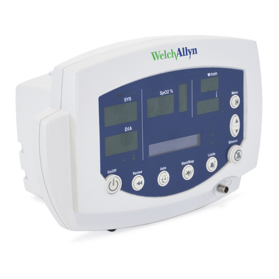
Welch Allyn 53000 Service Manual
Vital signs monitor 300 series
Hide thumbs
Also See for 53000:
- Service manual (78 pages) ,
- Directions for use manual (94 pages) ,
- Directions for use manual (86 pages)
Table of Contents
Advertisement
Advertisement
Table of Contents

Related Manuals for Welch Allyn 53000


Summary of Contents for Welch Allyn 53000
- Page 1 Vital Signs Monitor 300 Series Service Manual...
- Page 2 Allyn. No other use, reproduction, or distribution of this publication, or any part of it, is permitted without written permission from Welch Allyn. Welch Allyn assumes no responsibility for any injury to anyone, or for any illegal or improper use of the product, that may result from failure to use this product in accordance with the instructions, cautions, warnings, or statement of intended use published in this manual.
-
Page 3: Table Of Contents
Welch Allyn monitor service utility ........ - Page 4 Welch Allyn Vital Signs Monitor 300 Series...
-
Page 5: Safety
130S29E), distributed for use with previous models of the Vital Signs Monitor, must not be used with the Model 300 Series. Use of any tool other than the Welch Allyn Monitor Service Utility (810-1784-XX) may set the monitor in an undefined and unrecoverable state. -
Page 6: Electrostatic Discharge (Esd)
If the monitor detects an unrecoverable problem, an error code and a brief message appear in the message display. Report all such errors to Welch Allyn. • While under warranty, the monitor must be serviced only by a Welch Allyn service technician. Electrostatic discharge (ESD) -
Page 7: Symbols
Service manual Safety Symbols The symbols illustrated on the following pages appear on the monitor or in this document. Documentation symbols WARNING Indicates conditions that could lead to illness, injury, or death. Caution In this manual, indicates conditions that could damage equipment or other property. Caution On the product, means “Consult accompanying documentation.”... - Page 8 Safety Welch Allyn Vital Signs Monitor 300 Series Printer door label Press to open the printer door Load paper this direction The monitor front panel controls are described in more detail throughout this document. Front panel controls Set alarm limits...
-
Page 9: Service Overview
Technical support services Welch Allyn offers the following technical support services: Telephone support Loaner equipment Service agreements Service training Replacement service parts Factory Service For information on any of these services, contact Welch Allyn at the Technical Support: numbers listed on page... -
Page 10: Returning Products
Service overview Welch Allyn VSM 300 Series Returning products To return a product for service, contact Welch Allyn Technical Support and request a Return Material Authorization (RMA) number. Note Welch Allyn does not accept returned products without an RMA. When requesting an RMA, please have the following information available: •... -
Page 11: Recommended Service Intervals
Service options Warranty service All repairs on products under warranty must be performed or approved by Welch Allyn. Refer all warranty service to Welch Allyn Factory Service or another authorized Welch Allyn Service Center. Obtain an RMA number for all returns to Welch Allyn Factory Service –... - Page 12 Service overview Welch Allyn VSM 300 Series The monitor runs a self-test and then displays the main software version number (M: X.XX.XX). Press repeatedly to cycle to the menu selection of interest. /min DIA (mmHg) 3 seconds SERVICE MODE Power-up Self-test...
-
Page 13: Functional Verification
Functional verification Functional verification overview This section describes the procedure for a complete functional test to support recommended preventive-maintenance schedules. The verification includes tests for a monitor configured with the printer, temperature, and options. Perform only the tests applicable to the actual configuration. A checklist of the functional tests is provided on “Checklist and test results report form”... - Page 14 Welch Allyn Monitor Service Utility (required for NIBP repair or replacement; not required for functional testing) 008-0842-XX Service Serial Cable (for use with the Welch Allyn Monitor Service Utility 810-1784-XX) WA 5088-01 Tycos air release valve and small bulb 600-0021-XX...
-
Page 15: Functional Verification Procedure
If the monitor is configured with the temperature option, connect the temperature probe and insert it into the probe well. • If you are using an optional Welch Allyn Model Calibration Tester, plug it in and set it to the values that match your tester model: Model... - Page 16 Functional verification Welch Allyn VSM 300 Series Note Depending on the charge level of the battery, the charge LED may be either flashing or steady. flashing indicates that the monitor is running on AC, the battery is charging, and the battery is charged to less than 90% capacity.
- Page 17 Service manual Functional verification e. Do not return the probe to the probe well. 2. If the SpO option is present: a. Verify that the SpO sensor cable is connected to the monitor. b. Verify that the current draw from the bench power supply is less than 800 mA. 3.
- Page 18 If the NIBP module is not properly characterized, the monitor could overinflate a neonatal cuff, which could create a hazard for neonatal patients. WARNING If you cannot characterize the NIBP module, remove the monitor from service immediately and return it to Welch Allyn for service. (See “Returning products”...
- Page 19 Service manual Functional verification Leak test This tests the NIBP system for abnormal leakage. If the NIBP system is leaking, check for leaks in the external plumbing before opening the case to look for internal leaks. If you determine that any NIBP module component is causing abnormal leakage, you must replace the NIBP module before returning the monitor to clinical use.
- Page 20 Functional verification Welch Allyn VSM 300 Series 7. Press several times to select 0 mmHg (0 kPa). The valve opens to release pressure. 8. Disconnect the neonate cuff. Pressure calibration verification This tests pressure readings on the monitor against a calibrated external pressure meter.
- Page 21 Service manual Functional verification 4. Press once to select 80 mmHg (10.7 kPa). The cuff quickly inflates to approximately 80 mmHg (10.7 kPa), and then settles at a slightly lower pressure level. Wait a few seconds for the pressure to stabilize. 5.
- Page 22 Functional verification Welch Allyn VSM 300 Series 2. Press once to select 80 mmHg (10.7 kPa). 3. Wait for the pump to start and stop. 4. Press once to select 150 mmHg (20 kPa). 5. Wait for the pump to start and stop.
- Page 23 Service manual Functional verification 2. Turn on the monitor. 3. Set the monitor to ADULT mode. a. Press once. b. Press repeatedly until ADULT appears. 4. Set the inflation target pressure to 270 mmHg (36 kPa). a. Press repeatedly until TARGET PRESSURE appears in the display window. b.
- Page 24 Functional verification Welch Allyn VSM 300 Series When the overpressure cutoff triggers, the pump stops, the dump and bleed valves open, and the monitor displays E40. Any subsequent button press shuts off the monitor. Due to NIBP implementation differences, this test does not verify overpressure Note cutoff in earlier NIBP versions.
- Page 25 Service manual Functional verification Printer Note This test is to be performed only as part of a complete functional verification procedure. 1. Put the monitor into Service Mode. 2. Verify that the printer has paper. 3. Press . Verify that a settings report prints, and that it contains no printed anomalies and no missing or faded sections.
- Page 26 Functional verification Welch Allyn VSM 300 Series...
- Page 27 Service manual Functional verification Note The tests described in this section are to be performed only as part of a complete functional verification procedure. Perform one of the following three SpO tests. Testing the monitor only (Nellcor SpO Use this procedure to test only the monitor SpO function.
- Page 28 Functional verification Welch Allyn VSM 300 Series Testing the sensor with the monitor Use this procedure to test the monitor SpO function while verifying a sensor. 1. Connect an SpO sensor to the simulator optical finger and to the monitor.
- Page 29 Use this procedure to test the temperature function while verifying the temperature probe. 1. If the Welch Allyn Calibration Tester is not already warmed up, warm it up as follows: a. Set the tester temperature to the following temperature: Model...
- Page 30 Functional verification Welch Allyn VSM 300 Series 6. Verify that the reading displayed on the monitor is as follows: Model Temperature 9600 106.0 °F ±0.4 °F (41.1 °C ±0.2 °C) 9600 Plus 105.8 °F ±0.4 °F (41.0 °C ±0.2 °C) 7.
-
Page 31: Nurse Call
Service manual Functional verification Nurse call Note The tests described in this section are to be performed only as part of a complete functional verification procedure. Relay verification With reference to the drawing and table below, use an ohmmeter to check the contact resistance at the output pins of the Nurse Call connector, while the monitor is in the alarm state and while the monitor is out of the alarm state. - Page 32 Functional verification Welch Allyn VSM 300 Series Battery Note This test is to be performed only as part of a complete functional verification procedure. 1. With the monitor power off, disconnect the battery substitution-cable connector. 2. Install and connect the battery.
- Page 33 The patient isolation test requires an AC Withstand voltage high potential (hi-pot) tester, such as the AR 3605 or equivalent. If this equipment is not available, Welch Allyn can perform the patient isolation test for you quickly, for a nominal fee.
- Page 34 Functional verification Welch Allyn VSM 300 Series 2. Connect the hi-pot DC input test cable between the return jack on the tester and the DC input connector of the monitor. 3. Test isolation between the Nurse Call and DC input: a.
-
Page 35: Checklist And Test Results Report Form
Service manual Functional verification Checklist and test results report form Use a copy of this form to track your progress through the functional verification. Pass Fail N/A) Test Result Battery charging Power-on self-test Beeper Monitor-off current (mA): Init/idle current (mA): Baseline current... - Page 36 Functional verification Welch Allyn VSM 300 Series Here is an example of verification results for a typical monitor. Pass Fail (or N/A) Test Result Battery charging charge symbol lit Power-on self-test normal ...
-
Page 37: Troubleshooting And Repair
Caution Replace parts, components, or accessories only with parts supplied or approved by Welch Allyn. The use of any other parts can lead to inferior monitor performance and will void the product warranty. - Page 38 NIBP module failure. Characterize NIBP. (See “NIBP characterization” on page 36.) If the error persists, return the monitor to Welch Allyn for service/ Error code E41 NIBP module failure. Verify all cable connections, and then cycle the power. If the error persists, replace the NIBP module.
- Page 39 Service manual Troubleshooting and repair Symptom Possible cause Suggested action Missing LED display. LED failure on the display board. Replace the display board. Erroneous LCD characters. LCD partially connected. Fully connect the LCD to the main board. Buttons on the right side of Screws attaching the display Tighten the screws.
-
Page 40: Requirements For Module-Level Repair And Replacement
WARNING If the NIBP module is not properly characterized, the NIBP cuff could overinflate, which could be hazardous to neonatal patients. The Welch Allyn Monitor Service Utility facilitates this characterization procedure. For more information, see “Characterizing NIBP”... -
Page 41: Welch Allyn Monitor Service Utility
Welch Allyn monitor service utility Overview The Welch Allyn Monitor Service Utility is a software tool for use, with the VSM 300 Series service manual, by biomedical technicians, clinical engineers, and other qualified service personnel, to update and repair VSM 300 Series monitors. - Page 42 For Windows 2000 and XP operating systems, the supported adapter is KEYSPAN USB serial adapter USA-19HS.) Warranty service All repairs on products under warranty must be performed or approved by Welch Allyn. Refer all warranty service to Welch Allyn Factory Service or another authorized Welch Allyn Service Center.
- Page 43 8. Connect the DB-9 connector on the serial cable to the serial port on the PC. 9. Start the utility: Start > Programs > Welch Allyn > Service Tool - VSM 300 10. Open the Options menu and select settings. If the status panel in the lower left corner displays “VSM 3 Available”, then the utility has connected to the VSM;...
- Page 44 Troubleshooting and repair Welch Allyn VSM 300 Series Note If Log I/O to file is enabled, the utility captures all communications between the VSM and the utility in the file io.log. This file continues to grow until the communications link is broken, because the utility is continuously checking for the presence of the VSM.
-
Page 45: Service Procedures
Service manual Troubleshooting and repair To configure to a different COM port 1. Right-click on the port you want. 2. Select Properties. 3. Select Port Settings. 4. Click Advanced. 5. Select a new COM Port Number. The port settings for the Keyspan adapter are explained in the documentation included with the device. - Page 46 Troubleshooting and repair Welch Allyn VSM 300 Series To characterize NIBP 1. Select Characterize NIBP. The utility displays the message "Choose Start to begin characterization". 2. Click Start, and follow the on-screen instructions. The utility attempts to place the monitor in the correct state for characterization: •...
- Page 47 Service manual Troubleshooting and repair • The Debug Log lists the most recent warning conditions that have occurred, up to the maximum log size. When the Event and Debug Logs reach maximum size, new data overwrites the oldest. • The Calibration & User Log provides the following categories of information: •...
- Page 48 Troubleshooting and repair Welch Allyn VSM 300 Series Event Log Debug Log...
- Page 49 If the version installed on the monitor is newer than what the utility supports, the status displays “Not supported”. Contact Welch Allyn Technical Service to obtain an updated version of this utility. The status also indicates whether the installed software and firmware versions are compatible with the update versions offered.
- Page 50 Troubleshooting and repair Welch Allyn VSM 300 Series Update the Monitor Caution If the update is interrupted, the VSM monitor might be left in an unusable state. To minimize the possibility of interruption during the update: • Do not run other applications on the PC during this process.
- Page 51 Service manual Troubleshooting and repair If updates are available, Update Status is either “Update required” or “Update Recommended”. 1. Connect the monitor to the AC power adapter and to the PC. 2. Start the utility. 3. Select Update Monitor. 4. To start a software update, click Update. The monitor reboots and proceeds with all available updates, beginning with the Monitor Boot.
- Page 52 Troubleshooting and repair Welch Allyn VSM 300 Series 5. When the software upload is complete, the Update Status and Upload Status messages display “Success”. Click Finish to cause the service tool to query the monitor and retrieve the newly installed monitor versions.
- Page 53 To view the file without printing, click Print, right-click on the file, and select Open. • To print the file, click Print, select the file, click Open, select a printer, and click Print. Sample Upgrade Record ------------------------------------------------------------------------ WELCH ALLYN SERVICE TOOL UPGRADE RECORD ------------------------------------------------------------------------ ------------------------------------------------------------------------ MONITOR INFORMATION ------------------------------------------------------------------------ Model:VSM 3 Serial Number:JA000164...
- Page 54 Troubleshooting and repair Welch Allyn VSM 300 Series Monitor HW0Not updatableCompatible ------------------------------------------------------------------------ UPDATE LOG ------------------------------------------------------------------------ March 15 2007 11:32:33 Monitor Main:1.20.00 Success March 15 2007 11:32:34 cmdSetVSM3ValidVersionPoem:03.20.00 Success March 15 2007 11:32:34 cmdSetVSM3ValidVersionSpo2:1.9.0.1 Success March 15 2007 11:32:34 cmdSetVSM3ValidVersionTemp:1.2 Success...
- Page 55 Service manual Troubleshooting and repair 1. After a hardware module has been replaced with a new version, run the service utility to accept the new configuration. To accept the new firmware, click Update. The dialog box opens as shown in the screen shot below. 2.
- Page 56 Troubleshooting and repair Welch Allyn VSM 300 Series Here, the monitor has been reset to accept the temperature module with firmware version 1.2. Notice that the Upgrade Status message displays “Update recommended”. In step 2, No was selected to accept the new temperature module without updating any software.
- Page 57 1. From the lower left corner of the Windows desktop, click Start > Control Panel > Add or Remove Programs 2. Click the Welch Allyn Service Tool. 3. Click Change/Remove. 4. After the program is removed, reboot or turn off the computer.
- Page 58 Troubleshooting and repair Welch Allyn VSM 300 Series...
-
Page 59: Disassembly Procedure
Disassembly procedure Procedures overview These procedures cover monitor disassembly and board removal. Unless otherwise noted, the assembly procedure is the reverse of the disassembly procedure. WARNING Electrical shock hazard. The battery can deliver currents sufficient to cause serious personal injury and to damage the monitor. When opening the monitor for any reason, always remove and disconnect the battery immediately, before proceeding with disassembly. - Page 60 Disassembly procedure Welch Allyn VSM 300 Series Connectors Caution All connectors are keyed or coded to facilitate proper connection. Take care to correctly align all connector halves before attempting to connect them. Connector types The procedures described below require you to disconnect and reconnect ZIF (zero- insertion force) connectors, squeeze-release connectors, and pressure connectors.
-
Page 61: Display Board Connector
Service manual Disassembly procedure Order of disconnection Main-board Connects With Main-board Connects With Connector Connector External DC Input * Printer data – CN3 External RS-232 * Printer power – CN1 Battery Display board – J1 NIBP board * Temperature board – J1 * SpO board –... -
Page 62: Remove And Disconnect The Battery
Disassembly procedure Welch Allyn VSM 300 Series Main board – J12 External Probe Remove and disconnect the battery 1. Remove the four screws securing the battery door. Four screws securing the battery door 2. Remove the battery door. 3. Slide the battery out of the battery compartment. This might require lightly shaking the monitor. -
Page 63: Separate The Front And Rear Chassis
Service manual Disassembly procedure Separate the front and rear chassis 1. Remove the three screws securing the rear chassis. Housing Screws 2. Place the unit upright, with the front of the unit facing you. 3. Tilt the top of the front chassis away from the rear chassis while lifting the front chassis, freeing the front chassis from the corner tab feature on the bottom left-hand corner of the rear chassis. -
Page 64: Disassemble The Front Chassis Assembly
Disassembly procedure Welch Allyn VSM 300 Series 5. Disconnect the display-board flex cable (J5) from the main board. Disconnect the display-board flex cable from the main board (J5). Slide the outer piece of the connector toward the cable to release the cable;... - Page 65 Service manual Disassembly procedure 5 screws securing the LED display board 2. Lift out the display board. 3. Remove the keypad. Printer button Reassembly notes If you are replacing the keypad and your monitor does not include the thermal printer option, the Printer button must be removed from the keypad before you reinstall the keypad.
-
Page 66: Remove The Lcd Display From The Main Board
Disassembly procedure Welch Allyn VSM 300 Series Printer button Remove the LCD display from the main board Disconnect the LCD display module from connector J6 on the main board... -
Page 67: Disassemble The Rear Chassis Assembly
Service manual Disassembly procedure Disassemble the rear chassis assembly... -
Page 68: Remove The Main Board
Disassembly procedure Welch Allyn VSM 300 Series Remove the main board 1. Disconnect the temperature module flex cable from J12 on the main board. Temperature module flex cable Main board J12 connector Unlatch the ZIF connector before removing or inserting the flex cable 2. - Page 69 Service manual Disassembly procedure Four screws securing the main board 3. Pull the lower right corner of the main board away from the rear chassis, just far enough to free the RS232 connector housing on the main board from the RS232 connector slot on the rear chassis.
- Page 70 Disassembly procedure Welch Allyn VSM 300 Series Order of disconnection Main-board Connects With Main-board Connects With Connector Connector Nurse call connector NIBP board * Printer data – CN3 * SpO board – J2 * Printer power – CN1 Speaker Battery (* Denotes optional hardware.)
-
Page 71: Disassemble And Remove The Nibp Assembly
Service manual Disassembly procedure J3 cable connector properly aligned with the J3 connector on the main board. The cable connector is slotted on the top side..and the flanged side down. J3 cable connector properly aligned with the J3 connector on the main board. The cable connector has latching tabs on the bottom side. - Page 72 Disassembly procedure Welch Allyn VSM 300 Series NIBP pump NIBP tubing connection points on the pump NIBP bleed valve NIBP dump valve NIBP tubing connection points NIBP pump power on the manifold connector POEM 1 NIBP modules use a flying NIBP pump power connector that is soldered Note to the board.
-
Page 73: Remove And Replace The Speaker
Service manual Disassembly procedure b. Remove the NIBP module. NIBP reassembly notes WARNING You must characterize the NIPB module whenever you replace any NIBP component (pump, tubing, air filter, check valve, or NIBP module). WARNING If the NIBP module is not properly characterized, the pump could overinflate a neonatal cuff, which could be hazardous to neonatal patients. - Page 74 Disassembly procedure Welch Allyn VSM 300 Series • Disconnect and remove the NIBP assembly. Note It is not necessary to remove the printer or the NIBP pump. 2. Remove the old speaker and gasket from the rear chassis by prying it loose.
-
Page 75: Remove And Disassemble The Printer Assembly
Service manual Disassembly procedure Remove and disassemble the printer assembly Power cable Data cable Printer PCB Printer paper Printer frame Printer door Roller Printer mechanism 1. Remove the printer door. a. Open the printer door and remove the roll of printer paper. b. - Page 76 Disassembly procedure Welch Allyn VSM 300 Series Spindles 2. Remove the printer assembly. Push the plastic legs of the printer assembly outward and pull the printer assembly forward to free it from the snap-in seating of the rear chassis bulkhead.
- Page 77 Service manual Disassembly procedure Printer legs 3. Remove the printer subassembly (printer mechanism, printer well, printer board, and cables). a. Turn the printer assembly upside-down, and release the ZIF connector latches (CN2) on the printer board. Printer flex cable ZIF connector latches b.
- Page 78 Disassembly procedure Welch Allyn VSM 300 Series Two screws securing the printer mechanism Printer mechanism d. Turn the printer assembly upside-down. e. Remove the screw securing the printer board to the printer frame. If you are replacing the printer board, remove the cables from connectors CN1 and CN3 for use on the replacement board.
- Page 79 Service manual Disassembly procedure the housing and with the front of the board secured under the tab on the front of the housing. Printer board parallel with the surface of the printer housing. Printer board resting evenly on the housing standoffs. Printer board inserted under the retaining tab on the printer housing.
- Page 80 Disassembly procedure Welch Allyn VSM 300 Series Paper guide and sensor reassembly The operator, while replacing the printer paper, can inadvertently push the paper guide and sensor out of the chassis, rendering the printer inoperable. Caution Do not disassemble the paper guide if it is properly attached to the printer chassis.
- Page 81 Service manual Disassembly procedure Paper sensor cable Paper sensor Slot When properly aligned, the paper sensor is visible through the hole in the top of the paper guide. (Not shown.) 4. Position the outer pins in the outer notches of the printer chassis, with the retaining pins just above the inner slots of the chassis.
- Page 82 Disassembly procedure Welch Allyn VSM 300 Series Paper cradle Guide pin a. Align the guide pin on the chassis with the hole on the bottom of the printer. The paper guide and the paper cradle on the plastic chassis must be flush.
-
Page 83: Disassemble The Temperature Module
Service manual Disassembly procedure Disassemble the temperature module Note Disassembly of the temperature module does NOT require removal of the main board. 1. Remove the temperature module from the monitor. a. Remove the two screws (located on the left side, inside the rear chassis) securing the module to the slots on the left side of the rear chassis. - Page 84 Disassembly procedure Welch Allyn VSM 300 Series Note For older monitors where the temperature cable is routed through a ferrite bead on the rear chassis: If the temperature cable is pulled through the slot and out of the ferrite bead, it will be difficult to reroute the cable through the bead.
- Page 85 Service manual Disassembly procedure Temperature cable connector slot Temperature cable connector d. Release the ZIF latches (J1) and disconnect the temperature cable. Note It is not necessary to remove the temperature probe-well housing when replacing the temperature module. Three screws securing the temperature probe-well housing Temperature cable ZIF connector...
- Page 86 Disassembly procedure Welch Allyn VSM 300 Series Temperature module reassembly notes To install the temperature board in the module housing: 1. Square the circuit board in the housing to fit the probe-well receiver into the top of the outside housing.
- Page 87 Service manual Disassembly procedure 2. Remove the SpO board. a. Remove the two screws securing the board to the side panel. Two screws securing the SpO board to the SpO assembly b. Disconnect J1 and J2. Caution To avoid stressing and damaging the J1 flex cable, disconnect the cable by gripping the J1 flex-cable connector with pliers and separating the connector halves without stressing or otherwise putting any pressure on the flex cable itself.
- Page 88 Disassembly procedure Welch Allyn VSM 300 Series Grip with pliers here, and separate the J1 connector halves. Never pull directly on the cable itself. reassembly notes (Nellcor) The J2 connector halves are keyed to prevent incorrect connection. However, to facilitate...
- Page 89 Service manual Disassembly procedure Disassemble the Masimo SpO assembly 1. Remove the SpO2 assembly from the rear chassis and disassemble as follows: a. Remove the four screws (located on the inside of the rear chassis on the right side) that secure the SpO2 assembly to the rear chassis. Four screws securing the SpO assembly to the rear chassis b.
- Page 90 Disassembly procedure Welch Allyn VSM 300 Series d. Remove the three screws (C) securing the circuit board to the plastic chassis. e. Remove the two screws (D) securing the SpO2 sensor flex to the connector housing. Slide the SpO2 sensor flex cable assembly out of the rails on the connector housing.
-
Page 91: Replacement Parts
Replacement parts This list includes field-replaceable service parts only. Use only accessories approved by Welch Allyn. Visit www.welchallyn.com. The use of any other accessories can result in inaccurate patient data, can damage the equipment, and can void your product warranty. - Page 92 Replacement parts Welch Allyn VSM 300 Series...
- Page 93 Service manual Replacement parts Rear case (standard configuration) Drawing Order Ref # number Description Notes 020-0621-XX NIBP module , POEM2 (contains pump adapter cable) 031-0150-XX PCB assembly, main board VSM III 5, 6 407560 Battery assembly 600-0517-XX Pad, foot, urethane, .44” d, .2” h, black, qty 2 020-0753-XX Gasket and speaker assembly 620-0403-XX Cable tie, nylon, .14”...
- Page 94 Replacement parts Welch Allyn VSM 300 Series...
- Page 95 Service manual Replacement parts NIBP pump and plumbing parts Drawing Order Description Ref # number 600-0179-XX Tubing, 1’, 0.125” I.D., 0.250 O.D., silicone 600-0396-XX Check valve, NIBP 680-0068-XX Pump, POEM NIBP, 6V, rolling 600-0520-XX Filter, NIBP 600-0043-XX Fitting, 1/8” ID tube, tee, nylon (not shown; POEM 1 only) 600-0178-XX Fitting, 1/8”...
- Page 96 Replacement parts Welch Allyn VSM 300 Series Temperature option Drawing Order number Description Notes Ref # 620-0394-XX Screw, #4-40, 3/4”, machine 630-0211-XX Outside housing, temperature module 630-0238-XX Inside panel, temperature module 620-0393-XX Screw, #4-20, 5/16”, thread-forming 21327-1000 PCB, temperature module...
- Page 97 Service manual Replacement parts option, Nellcor Drawing Order Ref # number Description Notes 010-0232-XX SpO connector panel assembly, Nellcor 031-0169-XX Board, SpO , Nellcor 3A 620-0047-XX Screw, #6-32, 1/4”, machine 660-0233-XX Cable assembly, SpO main interface Nellcor...
- Page 98 Replacement parts Welch Allyn VSM 300 Series option, Masimo Drawing Order Ref # number Description Notes 630-0278-XX SpO2 connector housing, VSMIII, Masimo, plastic 031-0160-XX SpO2 subassembly board, Masimo MS-11 620-0393-XX Screw, #4-20 X .31, PNH, PHH, ZN, Plastite 48-2 660-0260-XX Cable assembly, SpO...
- Page 99 Service manual Replacement parts Printer option Drawing Order Ref # number Description 630-0213-XX Printer door without roller 630-0214-XX Frame, printer assembly 620-0149-XX Screw, printer door/roller 2-28 x 1/4” 620-0165-XX Screw, Plastite, 0.312, 2-28, thread-forming 532012-000 PCB, printer 532013-000 Printer mechanism, with roller 660-0229-XX Cable, printer data 660-0228-XX...
- Page 100 Replacement parts Welch Allyn VSM 300 Series Order number Description Notes Labels 680-0085-XX Overlay, front panel, 53000, international 680-0079-XX Overlay, front panel, 5300P, international 680-0082-XX Overlay, front panel, 530T0, international 680-0083-XX Overlay, front panel, 530TP, international 680-0080-XX Overlay, front panel, 53N00, international...
- Page 101 Service manual Replacement parts Order number Description Notes Labels 714891 Label speaker, Caution VSM 300, Italian 714892 Label speaker, Caution VSM 300, Polish 714920 Label speaker, Caution VSM 300, Portuguese 714893 Label speaker, Caution VSM 300, Spanish 714895 Label speaker, Caution VSM 300, Swedish...
- Page 102 AC power adapter (8V, 0.75A, 240 VAC EU) AC power adapter (8V, 0.75A, 240 VAC NZ, Australia) Notes 1 Requires Welch Allyn monitor service utililty application (810-1784-XX) and serial cable (008-0842-XX) when the replacement board software version is different from the existing board.
-
Page 103: Updates And Service Bulletins
Eventually, the DC power cord might disconnect from the power input connector on the back of the monitor. To prevent this, contact Welch Allyn and order part number 008-0895-XX, VSM 300 Series DC Power Cable Clamp. This item, which is provided at... - Page 104 Updates and service bulletins Welch Allyn VSM 300 Series...
- Page 105 Service Manual characterization procedure 36 test 14 chart of screws 55 checklist 31 component-level repair voids warranty 5 configurations available 6 connectors 56 controls synopsis 4 CSA certification 3 disassembling the front chassis half 60 disassembly procedure 55 displays synopsis 4 earlier versions this manual does not apply 5 equipment 9...
- Page 106 Welch Allyn Vital Signs Monitor 300 Series returning products 6 return-material authorization 6 RMA 6 screws 55 separating the chassis halves 59 service in warranty 7 service interval 7 service menu 7 service utility 37 services available 5 technical support services 5...