Advertisement
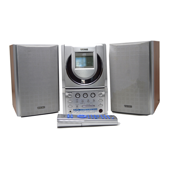
EX-M3/MC-D3
NOTES
NOTES
PC board shown are viewed from parts side.
The parts with no reference number or no parts number
in the exploded views are not supplied.
As regards the resistors and capacitors, refer to the
circuit diagrams contained in this manual.
!
Parts marked with this sign are safety critical
components. they must be replaced with identical
components - refer to the appropriate parts list and
ensure exact replacement.
Parts of [ ] mark can be used only with the version designated.
[US]: U.S.A (EX-M3) [E]: EUROPE (MC-D3)
[UK]: U.K. (MC-D3)
CD Receiver System
CONTENTS
CONTENTS
2
3
4
6
10
16
18
Advertisement

Related Manuals for Teac EX-M3


Summary of Contents for Teac EX-M3
-
Page 1: Table Of Contents
6 WIRING DIAGRAM components - refer to the appropriate parts list and 7 INCLUDED ACCESSORIES ensure exact replacement. Parts of [ ] mark can be used only with the version designated. [US]: U.S.A (EX-M3) [E]: EUROPE (MC-D3) [UK]: U.K. (MC-D3) -
Page 2: Safety Information
EX-M3/MC-D3 1 SAFETY INFORMATION SAFETY INFORMATION This product has been designed and manufactured according to FDA regulations " title 21, CFR, chapter 1,subchapter J,based on the Radiation Control for Health and Safety Act of 1968" and is classified as class 1 laser product. There is not hazardous invisible laser radiation during operation because invisible laser radiation emitted inside of this product is completely confined in the protective housings. -
Page 3: Specifications
EX-M3/MC-D3 2 SPECIFICATIONS CD PLAYER Section Pickup: 3-beam pick-up Wavelength : 790 nm 20 Hz ~ 22 kHz Audio frequency response : CASSETTE DECK Section 4 track, 2 channel stereo Track System: 4.76 cm/sec Tape Speed: 0.4% or less Wow and Flutter:... -
Page 4: Adjustment And Checks
1. Set the function switch to the AM position. 2. Connect the test loop antenna across the output of the signal generator. 3. Connect the oscilloscope to the speaker terminal. 4. Set the signal generator as listed in the alignment chart. EX-M3 TUNER PCB... - Page 5 EX-M3/MC-D3 3-1-3 FM/AM alignment chart SG SETTING TUNER SETTING ADJUSTMENT POINT ADJUSTMENT ITEM 87.5MHz 87.5MHz Adjust for max.output. 1. FM band 1kHz, +/-22.5kHz dev. 90MHz 90MHz 1kHz, +/-22.5kHz dev. Adjust for max. output 106MHz and best waveform. 106MHz 1kHz, +/-22.5kHz dev.
-
Page 6: Exploded View And Parts List
EX-M3/MC-D3 4 EXPLODED VIEWS AND PARTS LIST EXPLODED VIEW - 1... - Page 7 EX-M3/MC-D3 EXPLODED VIEW-1 REF. NO DESCRIPTION REMARKS PARTS NO. 05-30EX0M300000 CD PCB ASSY - UL [US] 05-30EX0M300010 CD PCB ASSY - CE [E] [UK] 56-07EX0M17B000 PCB BRACKET 05-07EX0M300000 POWER PCB ASSY TUNER PCB ASSY 05-02EX0M300000 05-23EX0M100000 O/C SWITCH PCB ASSY...
- Page 8 EX-M3/MC-D3 EXPLODED VIEW - 2...
- Page 9 EX-M3/MC-D3 EXPLODED VIEW-2 REF. NO DESCRIPTION REMARKS PARTS NO. 56-14EX0M30A000 CD DOOR 56-58EX0M118000 BADGE LOGO - TEAC 56-57EX0M320010 DISPLAY LENS 57-26EX0M300020 FILTER SHEET 56-57EX0M300000 BACK LIGHT LENS 56-07EX0M35G000 CD DOOR PLATE (CHROME) 05-16EX0M300000 LED PCB ASSY 56-07EX0M309000 BACK LIGHT LENS BRACKET...
-
Page 10: Pc Boards And Parts Lists
EX-M3/MC-D3 5 PC BOARDS AND PARTS LIST TUNER PCB ASSY REMARKS REF. NO PARTS NO. DESCRIPTION 05-02EX0M300000 TUNER PCB ASSY 48-02EX0M100220 TUNER PCB 32-022102800020 FERRITE BAR 10X80MM CON2 43-012200170120 WAFER 7 PINS 180C 31-028107000110 CER.FILTER SFE10.7AM 31-026450010110 CER.FILTER SFU450B 27-501802101020... - Page 11 EX-M3/MC-D3 TUNER PCB R/P PCB...
- Page 12 EX-M3/MC-D3 CD PCB ASSY REF. NO PARTS NO. DESCRIPTION REMARKS 05-30EX0M300000 CD PCB ASSY -UL [US] 05-30EX0M300010 CD PCB ASSY -CE [E] [UK] 48-30EX0M100222 CD PCB 43-012150160320 WAFER 6PIN P=1.5MM CON305 43-022200150120 WAFER 5PIN P=2MM CON410 43-022100216120 WAFER 16P P=1MM...
- Page 13 EX-M3/MC-D3 CD PCB D423 C414 Q410 CN401 CON413 D422 J428 D403 R418 R417 R419 CON406 D408 R420 D409 Q404 D410 C401 D411 R444 IC401 D413 D412 R125 C402 R415 D415 D414 C412 R427 Q402 R416 CN402 D416 D407 Q405 R428...
- Page 14 EX-M3/MC-D3 POWER PCB ASSY REF. NO PARTS NO. DESCRIPTION REMARKS 05-07EX0M300000 POWER PCB ASSY 48-07EX0M300120 POWER PCB C757 26-017680850121 CE-25V 6800UF C769 26-017100650121 CE-10V 1000UF C808 26-017100850121 CE-25V 1000UF CON701 43-012200170120 WAFER 7PIN P=2MM CON702,704 43-012200150120 WAFER 5PIN P=2MM CON703...
- Page 15 EX-M3/MC-D3 POWER PCB R804 Q730 CON701 C787 R802 R803 Q716 CON702 C788 CON703 C747 R783 Q717 C765 D715 R784 R791 R789 R785 R790 ZD705 Q725 Q724 R702 C766 C764 R788 C775 C782 CON705 C771 R775 Q715 Q713 C891 C774 C767...
-
Page 16: Wiring Diagram
EX-M3/MC-D3 6 WIRING DIAGRAN TO DISPLAY PCB CON1 TO KEY PCB CON503 CD PCB CON413 TO KEY PCB CON501 CN401 CON406 TO KEY PCB CON502 TO TUNER PCB CON1 TO TUNER PCB CON2 TO CD DECK CON403 CON404 TO POWER PCB CON702... - Page 17 EX-M3/MC-D3 TO CASS DECK POWER PCB CON703 TO TUNER PCB CON3 CON704 CON707 CON708 TO CASS DECK TO H/P PCB TO TRANSFORMER...
-
Page 18: Included Accessories
EX-M3/MC-D3 6 INCLUDED ACCESSORIES INCLUDED ACCESSORIES REF. NO PARTS NO. DESCRIPTION REMARKS 77-20EX0M300020 INSTRUCTION BOOK-E [US] INSTRUCTION BOOK-E/F/S/I [E] [UK] 77-20EX0M300120 02-17EX0M300000 REMOTE CONTROL... - Page 19 TEAC NEDERLAND BV Oeverkruid 15,NL-4941 W Raamsdonksveer, Nederland Phone:0162-510210 TEAC BELGIUM NV/SA. c/o TEAC NEDERLAND BV, Oeverkruid 15, NL-4941 W Raamsdonksveer, Nederland Phone:+31-162-510860 TEAC ITALIANA S.p.A. Via C, Cantu 11, 20092 Cinisello Balsamo, Milano, Italy Phone:02-66010550 TEAC AUSTRALIA PTY., LTD.